

Camera module
a technology of camera module and camera body, which is applied in the direction of camera focusing arrangement, printers, instruments, etc., can solve the problems of difficult construction of miniature camera modules, and achieve the effects of reducing the amount of current consumed in order to move reducing the occurrence of tilting, and reducing the generation of friction between the base and the first and second movers
Active Publication Date: 2021-03-25
LG INNOTEK CO LTD
View PDF0 Cites 4 Cited by
- Summary
- Abstract
- Description
- Claims
- Application Information
AI Technical Summary
Benefits of technology
The patent describes a camera module that uses support balls to reduce friction and stabilize movement in the optical-axis direction. This reduces the amount of electricity consumed and prevents tilting, allowing for efficient auto-focusing and zoom-up functions. A stopper is also included to limit the movement of the support balls and prevent malfunctions and noise. Overall, this invention creates a camera module with a simple structure and improved performance.
Problems solved by technology
Since miniature camera modules have a limited size, there is a problem in that it is difficult to construct miniature camera modules such that they perform a zoom-up function of the type implemented in general large-scale cameras.
Method used
View moreImage
Smart ImageViewing Examples

Examples
Embodiment Construction
[0165]Various embodiments have been described in the best mode for carrying out the disclosure.
INDUSTRIAL APPLICABILITY
[0166]A camera module according to embodiments may be applied to portable devices such as, for example, mobile phones, smartphones, tablet PCs, or laptop computers.
Login to View More PUM
 Abstract
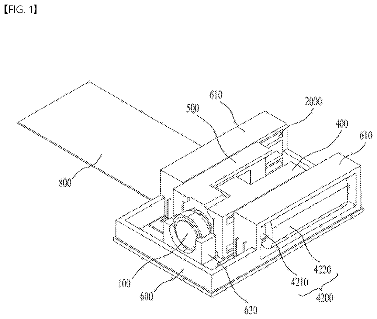
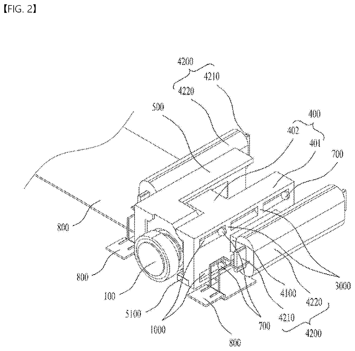
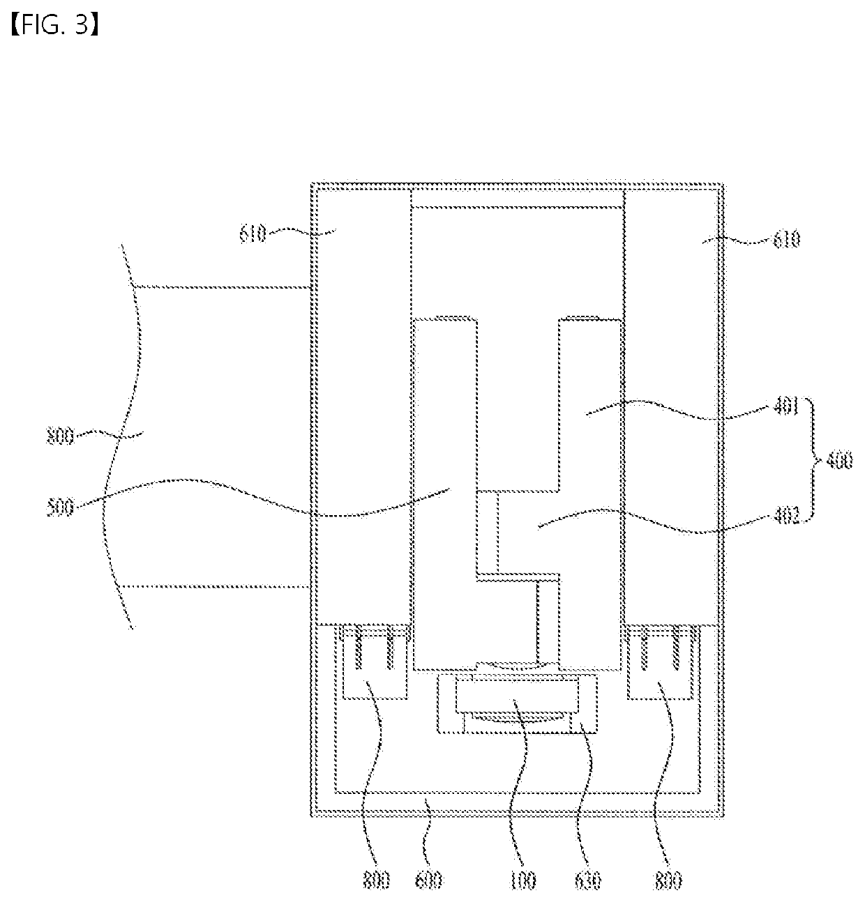
A camera module includes first to third lens groups; a first mover configured to move the second lens group in the optical-axis direction; a second mover configured to move the third lens group in the optical-axis direction; a base accommodating the first mover and the second mover; a support ball disposed to be in rolling contact with the first mover, the second mover, and the base, the support ball supporting movement of the first mover and the second mover relative to the base; a driving magnet coupled to each of the first mover and the second mover; and a coil part coupled to the base, the coil part being disposed to face the driving magnet, and wherein an entirety of a surface of the driving magnet that faces the moving coil serves as a first pole.
Description
TECHNICAL FIELD[0001]Embodiments relate to a camera module configured to perform auto-focusing and zoom-up functions.BACKGROUND ART[0002]The content described in this section merely provides background information regarding embodiments, and does not constitute the conventional art.[0003]Mobile phones or smartphones equipped with camera modules that take an image or a video of an object and store the same have been developed. In general, a camera module may include a lens, an image sensor module, and a lens-moving device for adjusting the distance between the lens and the image sensor module.[0004]Mobile devices, such as mobile phones, smartphones, tablet PCs, and laptops, have built-in miniature camera modules. Camera modules may perform an auto-focusing function of adjusting the distance between an image sensor and a lens to control the focal length of the lens.[0005]Meanwhile, camera modules may also perform a zoom-up function, i.e. a function of photographing an object located a ...
Claims
Login to View More Application Information
Patent Timeline
 Patent Type & AuthorityApplications(United States)
IPC IPC(8): H04N5/225G03B13/36G03B17/12
CPCH04N5/2254H04N5/2253G03B17/12G03B13/36G03B5/00G03B30/00G03B3/10G03B2205/0046G03B2205/0069H04N23/55G03B2213/00H04N23/54
InventorKANG, JONG HYUN
OwnerLG INNOTEK CO LTD