
Wearable antenna and intra-uterine monitoring system

a technology of intrauterine monitoring and wearable antennas, which is applied in the field of wearable antennas and to intrauterine monitoring systems, can solve the problems of insufficient energy being delivered to implantable sensors, uncomfortable and unfriendly users, and inability to enable real-time long-term in-vivo monitoring, etc., and achieve the effect of improving electromagnetic interaction

Active Publication Date: 2021-04-01
UNIV OF SOUTHAMPTON
View PDF11 Cites 1 Cited by
  • Summary
  • Abstract
  • Description
  • Claims
  • Application Information

AI Technical Summary

Benefits of technology

This patent describes a wearable antenna that can receive data from an implantable sensor in a uterus. The antenna is designed to improve the interaction between the two devices, with a undulating shape to minimize interference. The design also provides a more reliable and robust belt coil, with better wireless performance and a wider working angle. Overall, this patent aims to improve the communication and power transfer between the wearable receiver and the implantable sensor device.

Problems solved by technology

The available data is mostly derived from snapshot technology and wired sensor probes, both of which do not enable real-time long-term in-vivo monitoring.
In a wireless energy transfer and communication system of this type, especially for intrauterine environment monitoring applications, data drop-out may occur because of a mismatch between the two (primary and secondary) antennas which results in insufficient energy being delivered to the implantable sensor for the measurement to take place, or because the acquired sensor data cannot be delivered from the implantable sensor to the wearable device.
There are also issues associated with wearing a loop antenna, which may be uncomfortable and unfriendly for the user.
For example, the wearing of a loop antenna may limit the user's normal activity and risk the antenna being broken.

Method used


Image

  • Wearable antenna and intra-uterine monitoring system
  • Wearable antenna and intra-uterine monitoring system
  • Wearable antenna and intra-uterine monitoring system

Examples


Embodiment Construction

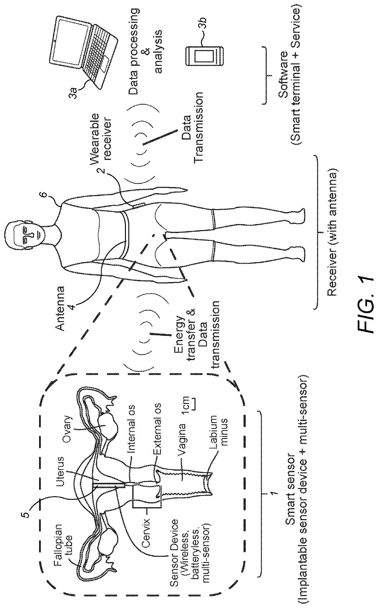
[0043]Referring to FIG. 1, a three-module structured multi-parameter in-vivo sensing platform for intra-uterine environment monitoring is shown. The platform comprises a smart sensor 1 (implantable sensor device, which is suitably shaped and dimensioned for implantation in a human uterus), an external, generally wearable, receiver 2 and monitoring software installed on suitable data processing hardware, such as a computer 3a or portable electronic device 3b. The smart sensor 1 is a fully implantable (within the uterus 5 of a human female body 6) sensor device incorporating multiple embedded biosensors (intended for measuring temperature, dissolved oxygen concentration (DOC) and pH). Temperature, DOC and pH are considered to be the three most important parameters to measure for this application because they maintain a homeostatic controlled balance of gases and acid-base which is vital to human life and reproduction. They are likely to determine the receptivity of the intra-uterine e...


PUM


Abstract

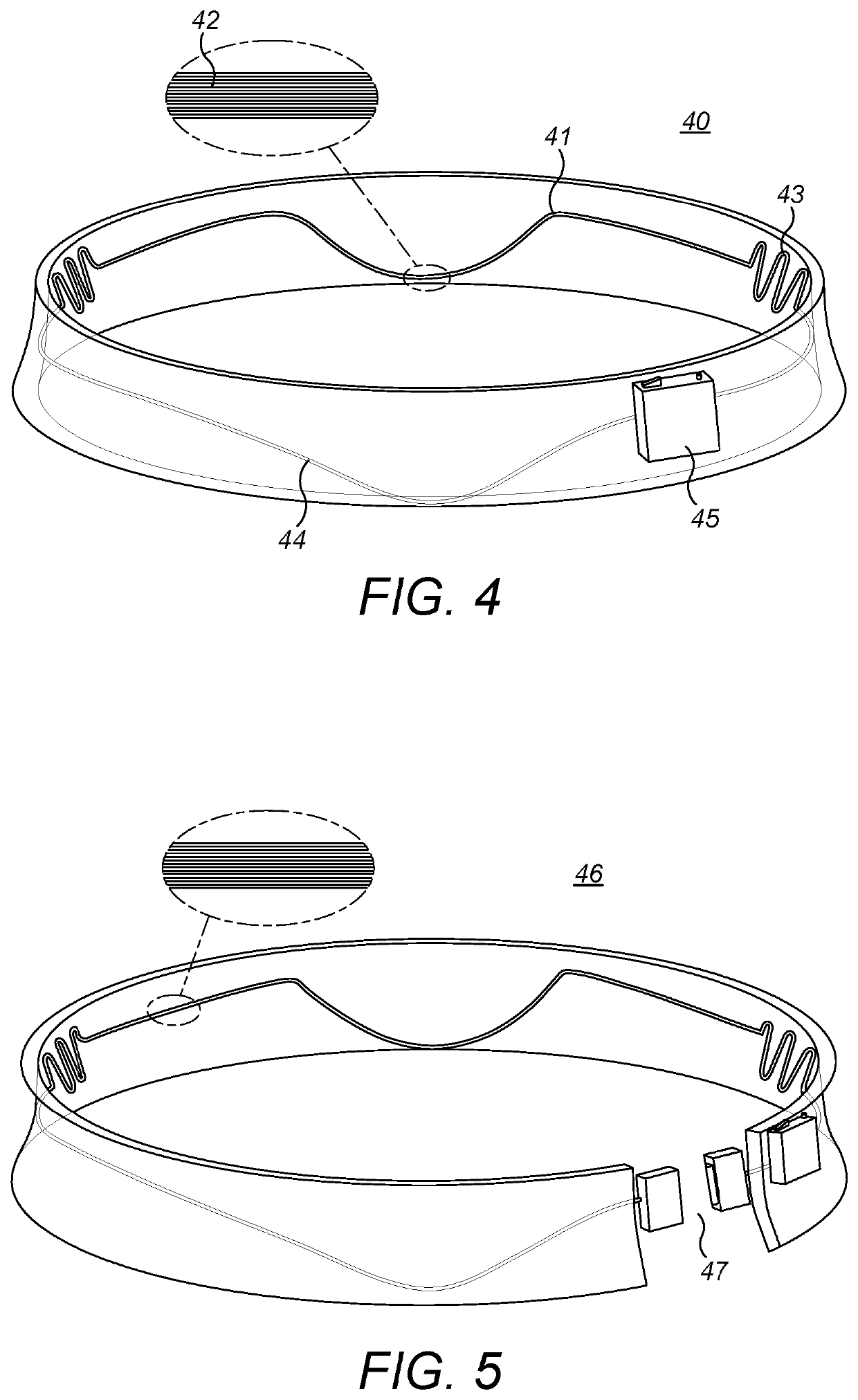
A wearable antenna is described, for wirelessly receiving sensor data generated by an implantable sensor device implanted in a uterus, the wearable antenna, in use, extending around the waist of the wearer's body, and having a downwardly extending portion for location at the front of the wearer's body. In this way, an improved electromagnetic interaction between the wearable antenna and the implantable sensor can be achieved. Further, the wearable antenna may have an undulating shape around at least a portion of the wearer's waist, to permit expansion and contraction of the wearable antenna about the wearer's waist.

Description

TECHNICAL FIELD[0001]The present invention relates to a wearable antenna, and to an intra-uterine monitoring system comprising such a wearable antenna. Embodiments of the present invention relate to a system for long-term, real-time, in-vivo measurement of biophysical parameters in a human uterus.BACKGROUND[0002]More than 30% of all human conceptions do not advance beyond 20 weeks of gestation. One in six couples suffer from infertility, and in around 25% of couples no clear reason is identified. Even after assistance from artificial reproductive technologies, take home baby rates have altered little in the last five to ten years. This may reflect the lack of understanding of the pathophysiological mechanisms and clinically relevant diagnostic approaches for interrogating uterine functions. An interaction between the intra-uterine environment (biophysical parameters, such as temperature, dissolved oxygen concentration and pH) and reproductive health is likely, but very little is kno...

Claims


Application Information

Patent Timeline
IPC IPC(8): H01Q1/27A61B5/00H01Q7/00
CPCH01Q1/273A61B5/4325H01Q7/00A61B5/0031
Inventor MORGAN, HYWELLU, SHILONGCHEONG, YING
Owner UNIV OF SOUTHAMPTON
Learn More