Attachment portion for an electric toothbrush replacement head

Active Publication Date: 2021-04-08
RANIR LLC
View PDF1 Cites 8 Cited by
  • Summary
  • Abstract
  • Description
  • Claims
  • Application Information

AI Technical Summary

Benefits of technology

[0008]In another embodiment, the drive shaft of the toothbrush drive unit may extend through the coupling member and abut the spring clip when the driv

Problems solved by technology

Axial retention can be a challenging aspect of such an arrangement if the rep

Method used


Image

  • Attachment portion for an electric toothbrush replacement head
  • Attachment portion for an electric toothbrush replacement head
  • Attachment portion for an electric toothbrush replacement head

Examples


Embodiment Construction

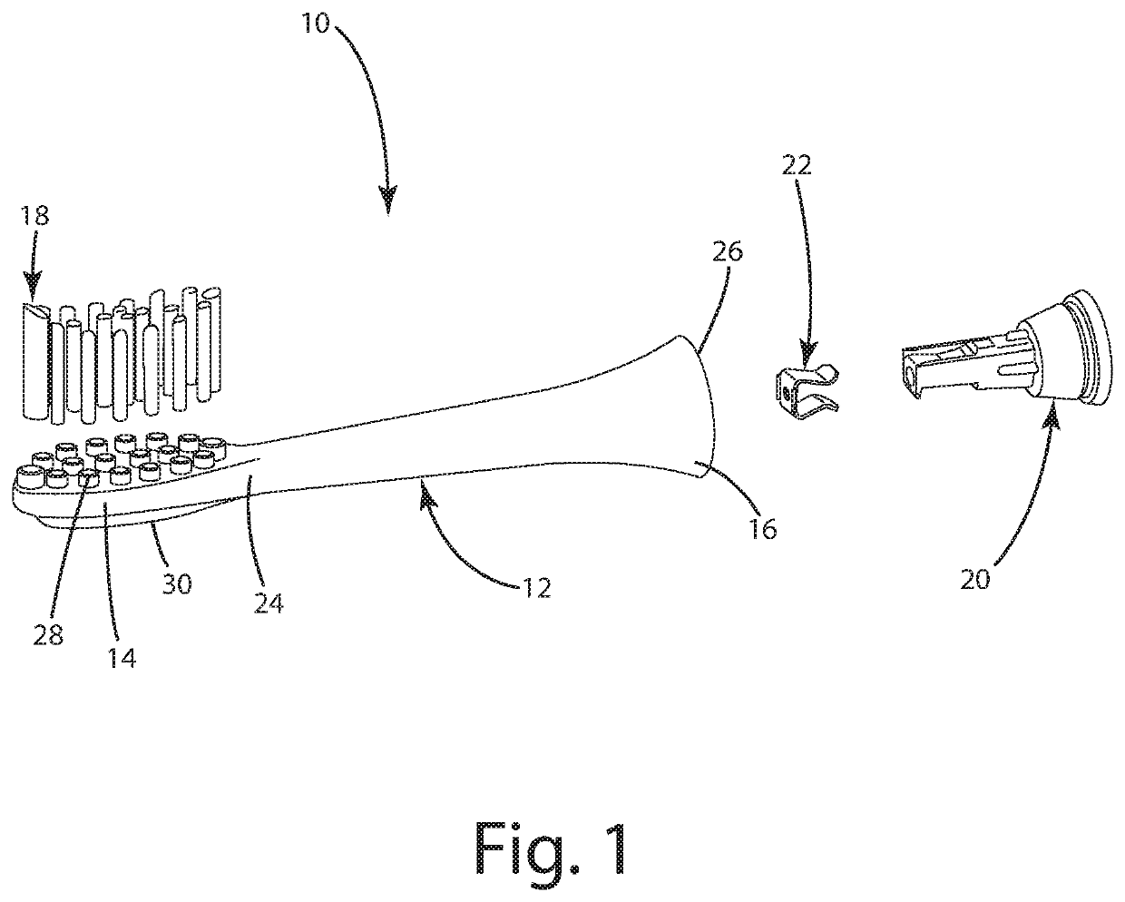
[0019]The embodiments of the invention described herein relate to a replacement head for an electric toothbrush, and more particularly to an attachment system for retaining the replacement head on the drive shaft of an electric toothbrush. A replacement head is shown generally in FIG. 1 and generally designated 10.

I. Overview

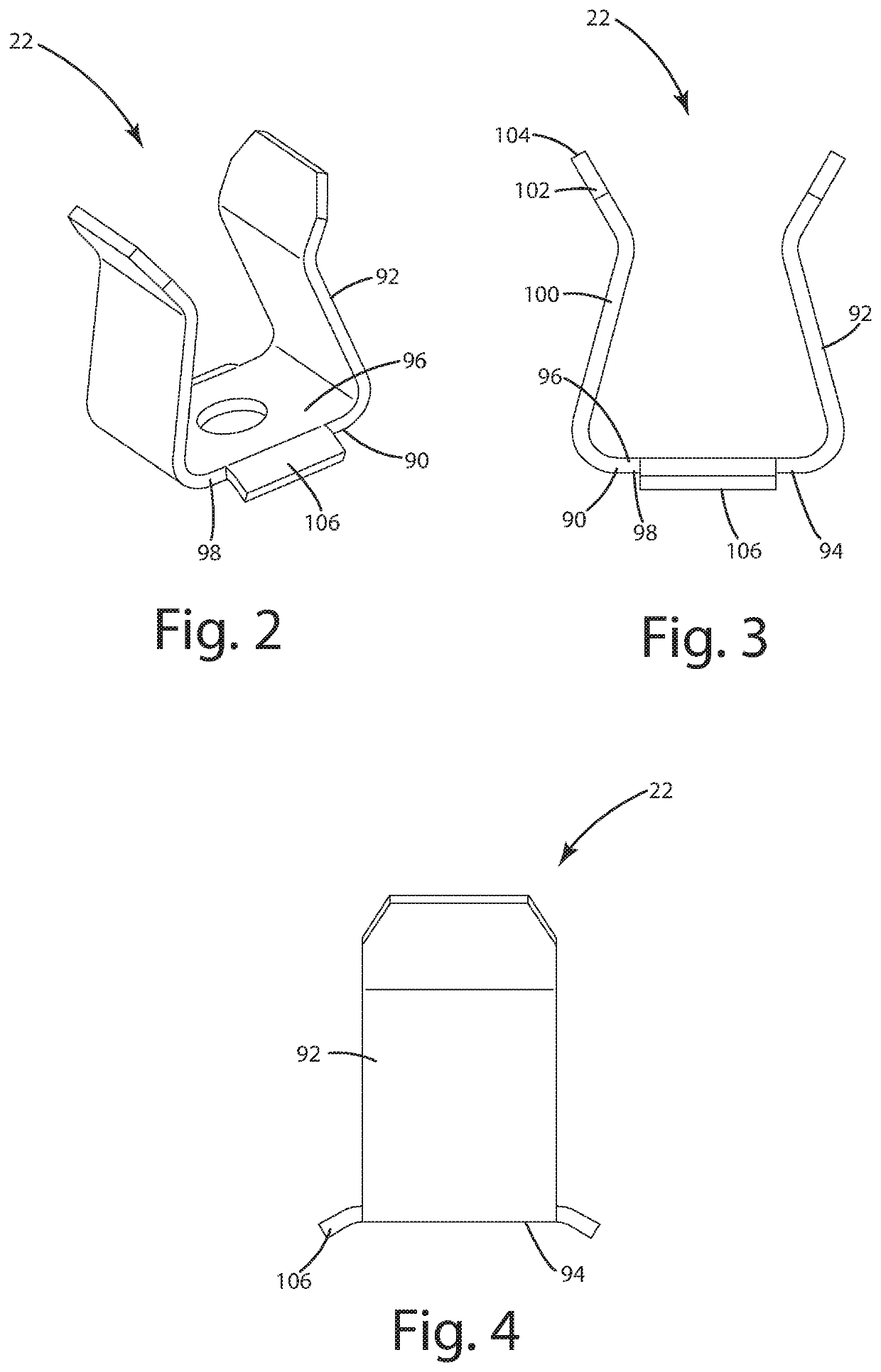
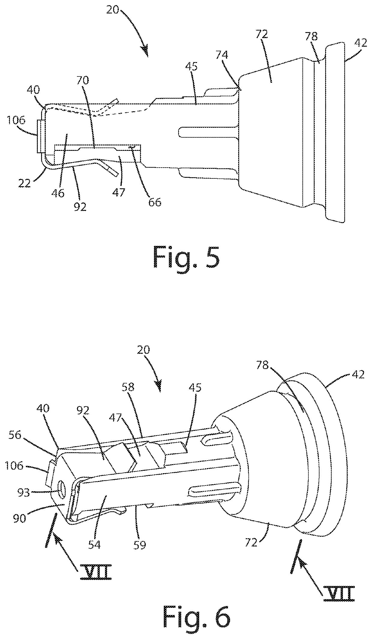
[0020]According to one embodiment, the replacement head 10 includes a sleeve or tube 12 having a head 14 at one end and a receptacle 16 at the opposite end. The head 14 includes a plurality of cleaning elements 18. The replacement head 10 further includes a coupling member 20 and spring clip 22 for insertion into the receptacle 16 of the sleeve 12.

II. Structure

[0021]Referring to FIGS. 1 and 9, the sleeve 12 is a tube having a first end 24 and a second end 26. The sleeve 12 may be formed from a molded plastic, with at least a portion at the second end 26 that is hollow. The sleeve 12 generally forms a longitudinal axis extending along the center of the sleeve len...


PUM


Abstract

A replacement toothbrush head includes a tubular sleeve having a brush at one end and a drive shaft receptacle at the opposite end. The receptacle extends into the sleeve from a mouth at a tube end to a shoulder spaced from the mouth within the tube. A coupling member is inserted into the receptacle, and a spring clip is positioned between the receptacle and the coupling member, the spring clip having a base positioned between the shoulder and the distal end of the coupling member and a pair of spring arms overlying the sidewall of the coupling member. At least one of the spring arms engages a flexible region of the coupling member such that the flexible region flexes to engage a drive shaft inserted into the coupling member and retain the replacement head on the drive shaft.

Description

BACKGROUND OF THE INVENTION[0001]The present invention relates generally to a replacement head for an electric toothbrush, and more particularly to an attachment portion for retaining the replacement head onto an electric toothbrush drive unit.[0002]Electric toothbrushes generally have a drive unit that includes a handle portion and a drive shaft. A drive mechanism is housed within the handle portion and the drive shaft extends from the handle portion and is driven rotationally or through a selected angle of oscillation by the drive mechanism. A removable replacement brush head assembly fits onto the extending driveshaft. The brush head assembly generally includes a hollow sleeve that supports the brush head at one end and includes an attachment portion at the opposite end. The attachment portion includes a coupling member that that fits into the attachment end of the sleeve. The drive shaft extends into the coupling member and is retained by the coupling member.[0003]The interface ...

Claims


Application Information

Patent Timeline
IPC IPC(8): A46B5/00A46B9/04A46B7/04A61C17/22
CPCA46B5/0095A61C17/222A46B7/042A46B9/04A46B2200/1066
Inventor DISHON, BRYAN J.
Owner RANIR LLC
Why Eureka
Try Eureka