
Axial Anti-backlash stepper/servo motor

a technology of axial backlash and stepper motor, which is applied in the field of motors, can solve the problems of reducing the position accuracy of objects, axial backlash and accuracy are not typically addressed, and the stepper motor is not designed for axial loads, so as to improve control and positioning, and reduce backlash

Active Publication Date: 2022-02-24
PACIFIC BEARING CORP
View PDF0 Cites 0 Cited by
  • Summary
  • Abstract
  • Description
  • Claims
  • Application Information

AI Technical Summary

Benefits of technology

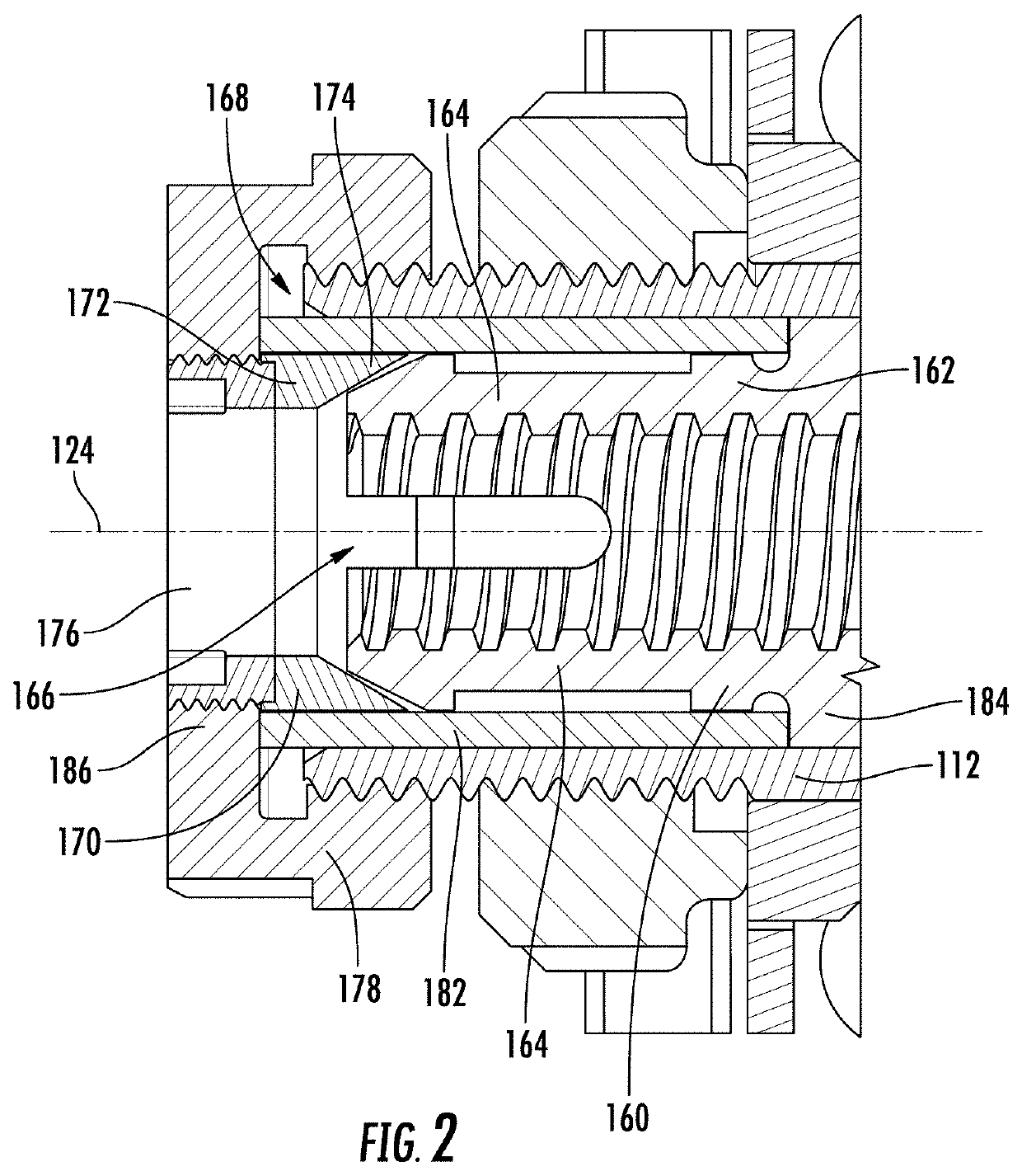
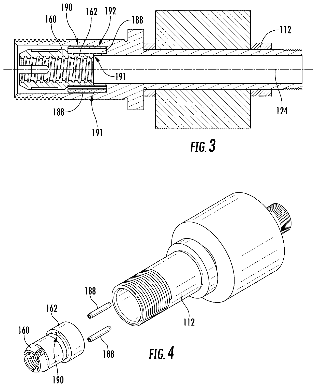
This patent is about improving motors, specifically stepper and servo motors. One improvement is reducing backlash to improve control and positioning. One solution is to use a drive nut with a non-round outer periphery that matches the non-round inner periphery of the rotor shaft, preventing relative angular displacement between the two. Another solution is a coupling pin that mechanically fixes the two components to prevent angular rotation between them. Another embodiment involves using a drive nut with an internal cavity and a rotor shaft with an internal cavity, and a coupling pin that extends into both cavities to prevent relative angular displacement. Overall, this patent provides improved design features for motors to make them more efficient and accurate.

Problems solved by technology

However, by nature, stepper motors are not design for axial loads.
Therefore, axial backlash and accuracy are not typically addressed.
Unfortunately, backlash in the system can reduce accuracy of the position of the object being driven by the motor.
One problem associated with these types of motors relates to the assembly method that relies on adhesive and a press fit to maintain the rotor position within the body.
Unfortunately, imprecise gaps are created between the bearings that support the rotor shaft and the magnetic core on the rotor shaft.
Thus, when the assembly of components is mounted within the motor body, backlash can occur between the rotor and the magnetic stator as a result of an imprecise assembly process.
More particularly, the components of the rotor are not consistently and accurately aligned with one another resulting in imprecise and improper alignment of the magnetic core of the rotor assembly and the magnetic stator.
Another problem with current designs is that a variable-force wave spring is used to axially secure the rotor assembly within the motor body and to allow for compensating for expansion of the components, e.g. due to thermal expansion.
Unfortunately, as determined by the instant inventors, this allows for a wide variation of movement in the system and contributes to backlash.
Also, during assembly, due to the use of a variable force spring, the inventors have identified that assemblers will often over tighten the assembly such that the wave spring becomes fully compressed and thus overloads the bearings in the axial direction resulting in premature wear of the bearings and increase resistance on the motor reducing the overall output force of the motor.
A third source of backlash occurs at the lead end of drive nut, where insufficient contact between the threads of the nut and the threads of the lead screw may occur.
This is particularly true as the drive nut wears with use.
Insufficient contact allows for backlash in the system as the drive nut will have a degree of rotation when changing direction where the drive nut is not engaging the threads of the lead screw.
A fourth source of backlash is lag stemming from the fit between rotor and drive nut.
As the pocket of the rotor and cooperating interface of the drive nut (often referred to as a boss) diverge from a line fit, the angular displacement increases, which is undesirable.
However, on the trailing end, e.g. the end opposite the nut, the lead screw is not radially supported.
The subsequent whipping action of the screw that is transverse to the rotational axis of the rotor is a factor of additional backlash.
A related issue is if the motor and / lead screw are not properly aligned in the end system, this can put transverse loads on the lead screw.
These transverse loads can cause slight deflection of the components of the nut such that the lead screw is not perfectly aligned with the rotational axis of the rotor shaft through which the lead screw extends.
This interaction can damage the threads of the lead screw.

Method used


Image

  • Axial Anti-backlash stepper/servo motor
  • Axial Anti-backlash stepper/servo motor
  • Axial Anti-backlash stepper/servo motor

Examples


Embodiment Construction

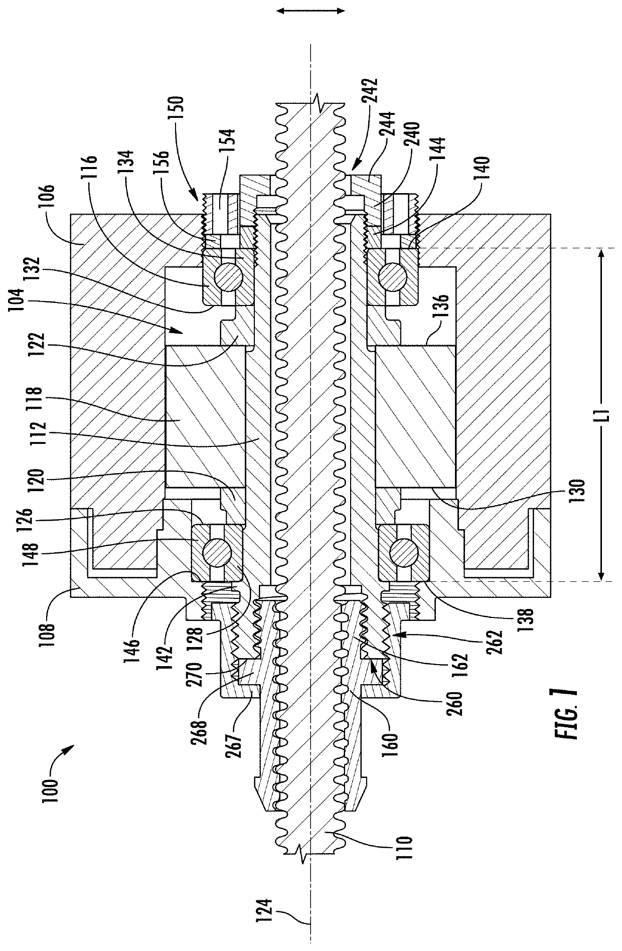
[0087]FIG. 1 is a cross-sectional illustration of a motor 100. The motor 100 includes a motor body 102 and a rotor assembly 104 located within the motor body 102. The motor body includes a stator 106 and a cover member 108 which may also be referred to herein as an end bell 108. The rotor assembly 104 is operably coupled to an externally threaded screw 110 (e.g. a lead screw) to drive the screw 110.

[0088]The rotor assembly 104 includes a rotor shaft 112, first and second bearings 114, 116, a magnetic core 118, and first and second axial standoffs 120, 122.

[0089]When mounted within the motor body 102, bearings 114, 116 radially support the rotor shaft 112 for rotation about a rotor shaft axis 124. The magnetic core 118 is operably angularly secured to the rotor shaft 112 such that rotational forces generated between the magnetic core 118 and the stator 106 cause the rotor shaft 112 to rotate. This angular securement may occur by way of a press fit or an adhesive between the rotor sha...


PUM


Abstract

A motor is provided. The motor includes a motor body and a rotor assembly. The rotor assembly includes a magnetic core mounted to a rotor shaft. The rotor assembly may include standoffs for accurately axially locating the magnetic core relative to rotor bearings. A drive nut adjustment arrangement may be provided. A mechanical interconnection between the drive nut and rotor shaft may be provided. A trailing end lead screw support may be provided. An axial preload arrangement may be provided to axially locate the rotor assembly within the motor body.

Description

[0001]This patent application is a continuation of U.S. PCT Patent Application No. PCT / US2020 / 027505, filed Apr. 9, 2020, which is now pending, which claims the benefit of U.S. Provisional Patent Application No. 62 / 833,375, filed Apr. 12, 2019, the entire teachings and disclosure of which are incorporated herein by reference thereto.FIELD OF THE INVENTION[0002]This invention generally relates to motors and particularly stepper / servo motors.BACKGROUND OF THE INVENTION[0003]Linear actuators that utilize stepper / servo motors are often used in highly precision systems where highly precise linear motion is desired. However, by nature, stepper motors are not design for axial loads. Therefore, axial backlash and accuracy are not typically addressed.[0004]Unfortunately, backlash in the system can reduce accuracy of the position of the object being driven by the motor.[0005]One problem associated with these types of motors relates to the assembly method that relies on adhesive and a press fi...

Claims


Application Information

Patent Timeline
Patent Type & Authority Applications(United States)
IPC IPC(8): H02K5/173H02K7/08H02K7/06H02K15/14H02K15/02F16H25/24
CPCH02K5/1732H02K7/083H02K7/06F16H2025/2075H02K15/02F16H25/24H02K15/14H02K2205/03F16H2025/2436
Inventor SCHROEDER, ROBERTSCHROEDER, JONATHAN R.LECRONE, TIMOTHY JOSEPHPROFFITT, KENTPROFFITT, KOLLINCUMMINGS, KEITH
Owner PACIFIC BEARING CORP
Learn More