
Illumination apparatus

a technology of illumination apparatus and illuminator, which is applied in the direction of optics, condensers, instruments, etc., can solve the problems of reducing the increasing the overall power consumption of displays, and reducing the application efficiency of micro-louver films, so as to improve the aesthetic quality, improve the uniformity of output across the output area of catadioptric optical elements, and improve the effect of illuminator and display uniform

Active Publication Date: 2021-04-08
OPTOVATE
View PDF0 Cites 6 Cited by
  • Summary
  • Abstract
  • Description
  • Claims
  • Application Information

AI Technical Summary

Benefits of technology

The patent describes a thin and efficient display that can produce multiple directional light output distributions using a small number of LEDs and catadioptric optical elements. This technology allows for improved display luminance and narrow illumination angles, resulting in a better viewing experience.

Problems solved by technology

Micro-louver films are inefficient because they work by absorbing light from the backlight in the unwanted display angular directions.
Such sizes and tolerances prevent application to very high resolution displays.
The black resin material absorbs a substantial amount of the emitted light, which reduces the efficiency and increases overall power consumption of the display.

Method used


Image

  • Illumination apparatus
  • Illumination apparatus
  • Illumination apparatus

Examples


Embodiment Construction

[0207]It would be desirable to provide a switchable illumination apparatus for display, display backlighting or for domestic or professional environmental lighting. Environmental lighting may include illumination of a room, office, building, scene, street, equipment, or other illumination environment.

[0208]Display backlighting means an illumination apparatus arranged to illuminate a transmissive spatial light modulator such as a liquid crystal display. The micro-LEDs of a display backlight may be provided with pixel information, for example in high dynamic range operation as will be described herein. However, in general pixel data is provided by the spatial light modulator.

[0209]Direct display means an illumination apparatus wherein the micro-LEDs are arranged to provide pixel image information, and no spatial light modulator is arranged between the illumination apparatus and observer.

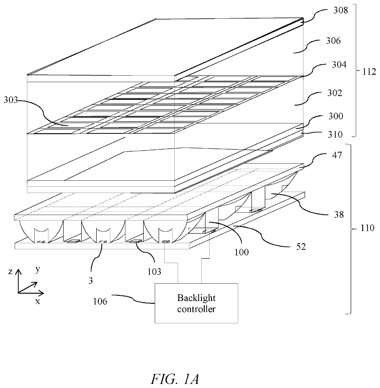
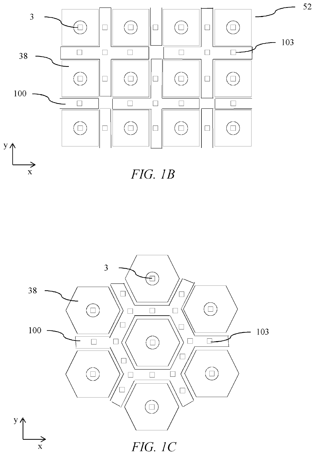
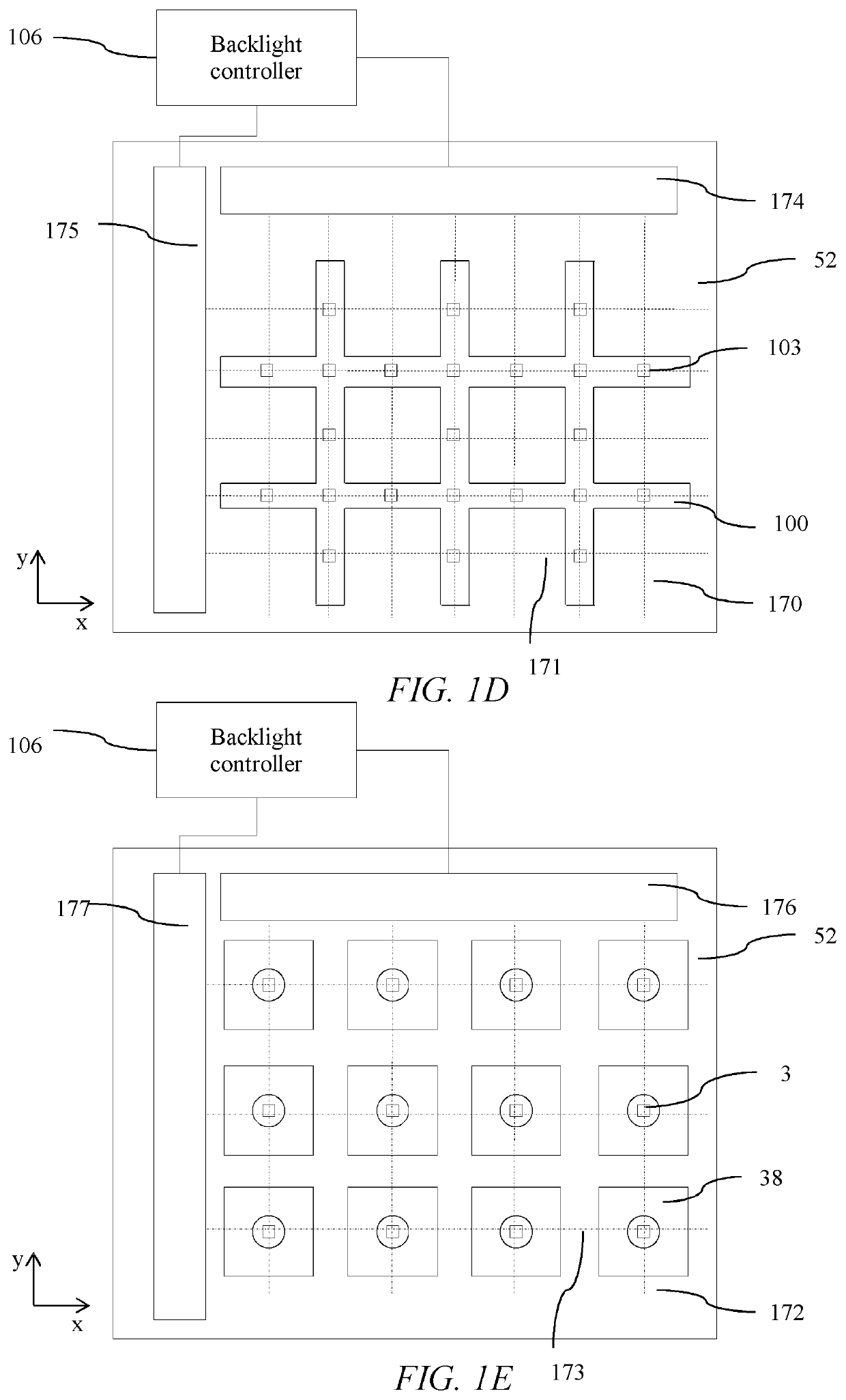
[0210]FIG. 1A is a schematic diagram illustrating in side perspective view a switchable directional...


PUM

PropertyMeasurementUnit
diameteraaaaaaaaaa
diameteraaaaaaaaaa
diameteraaaaaaaaaa

Abstract

A switchable directional illumination apparatus comprises first and second arrays of LEDs, some of which are micro-LEDs; an aligned catadioptric micro-optic array and an aligned light guide array. In a first mode a narrow angular output is provided by a first micro-LED array and catadioptric micro-optics. In a second mode a wider angular output is provided by the second LED array and light guides. A thin and efficient illumination apparatus may be used for switching illumination in environmental lighting, display backlighting or direct display.

Description

TECHNICAL FIELD[0001]The present disclosure relates to an apparatus comprising a plurality of addressable light-emitting elements aligned to a plurality of optical elements. Such an apparatus may be used for switchable environmental lighting, for switchable indoor or outdoor electronic display screens, or for a switchable backlight to an LCD display.BACKGROUND[0002]Displays with wide directional light output distributions are typically used to achieve comfortable display viewing from many different viewing angles. Such displays are desirable for multiple users to share image content, and for displays where the viewing position is not substantially fixed in relation to the display centreline.[0003]By way of comparison displays with narrow directional light output distributions are typically used to provide image data for the eyes of users over reduced viewing angles. Such displays are typically used to achieve privacy display (where images that may be seen by snoopers are suppressed)...

Claims


Application Information

Patent Timeline
Patent Type & Authority Applications(United States)
IPC IPC(8): G02F1/1335G02F1/13357
CPCG02F1/133607G02F1/133609G02F1/133603G02B19/0066G02B19/0028G02F1/133612G02F1/133626H01L25/0753H01L33/58H01L33/0095
Inventor WOODGATE, GRAHAM J.HARROLD, JONATHAN
Owner OPTOVATE
Learn More