
Method for Operating A Control Device, Control Device and Computer Program Product

Active Publication Date: 2021-04-08
OPENSYNERGY
View PDF0 Cites 0 Cited by
  • Summary
  • Abstract
  • Description
  • Claims
  • Application Information

AI Technical Summary

Benefits of technology

The invention reduces the cost of developing safety-critical functions, which means it becomes easier and less expensive to create these functions. This allows for more complex safety-critical functions, such as those needed for autonomous driving, to be developed with less effort and cost.

Problems solved by technology

Non-safety-critical functions can run on an operating system that is not qualified for functional safety.
However, such a system is not suitable for displaying safety-critical functions on a display.
To qualify the operating system and all affected device drivers may become very expensive or even impossible, e.g. if the underlying hardware device is not qualified.

Method used


Image

  • Method for Operating A Control Device, Control Device and Computer Program Product
  • Method for Operating A Control Device, Control Device and Computer Program Product
  • Method for Operating A Control Device, Control Device and Computer Program Product

Examples


example 1

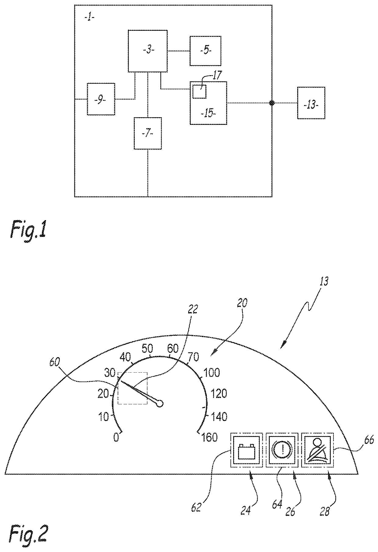
[0093] The supervision of the output (display on the screen) of safety-critical symbols that need to be shown to the vehicle driver by an instrument cluster component. One of the safety-critical functions is to display safety-critical icons on the instrument cluster screen—the requirements tell that such a symbol shall be shown within a certain time period when the respective command has been received. Supervision of such a function means to validate each output, which is a rendered screen image, by finding the critical symbols in the image data. The memory location is determined by reading from the display hardware registers. The a-priori information used for efficient implementation of such a supervision function is location, colors and shape of the icon.

[0094]Example 2: The supervision of the display of the current speed value on an instrument cluster display. The second monitoring module 46 needs the a-priori information about the speedometer instrument and speed needle geometry...


PUM


Abstract

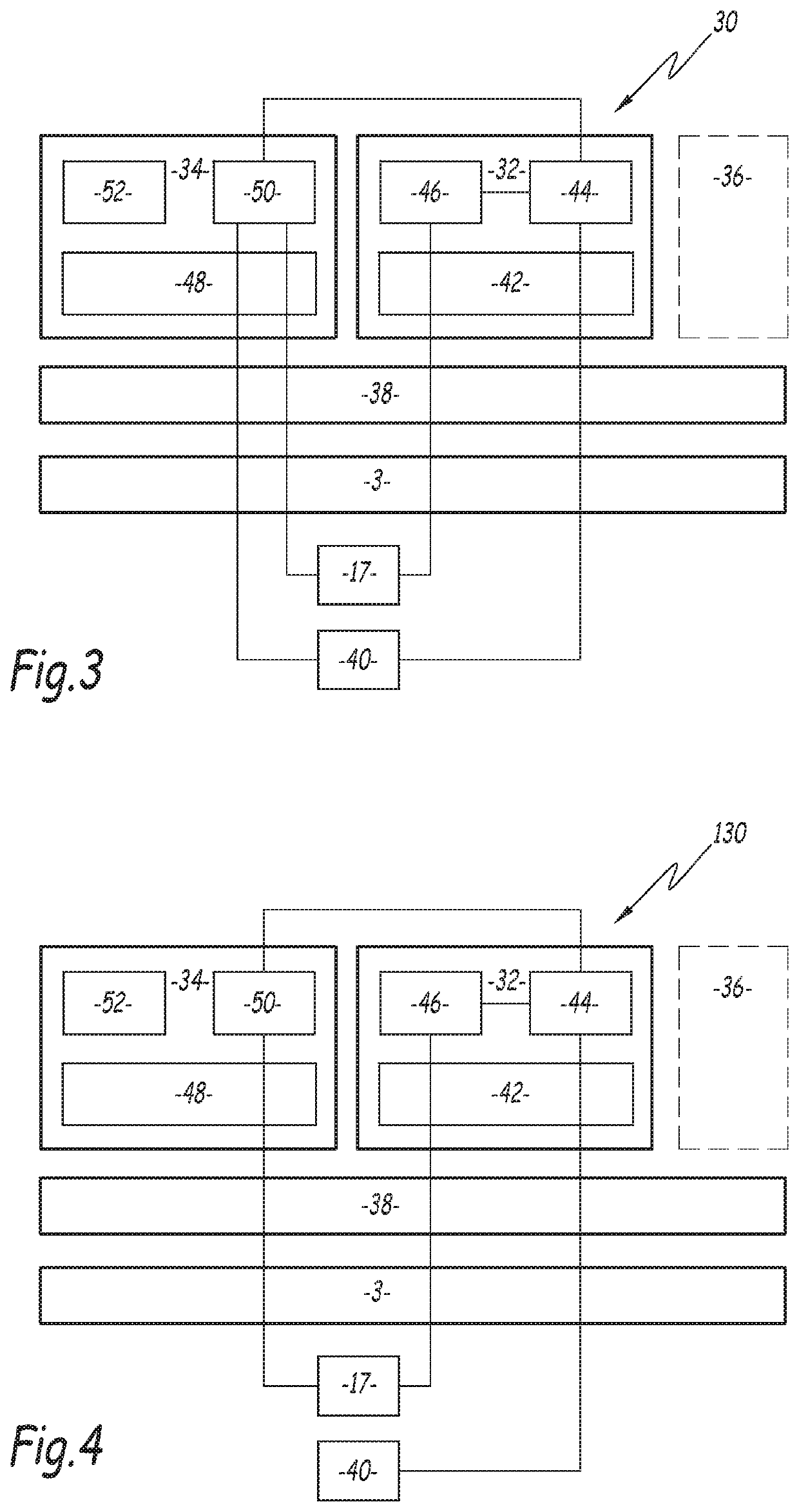
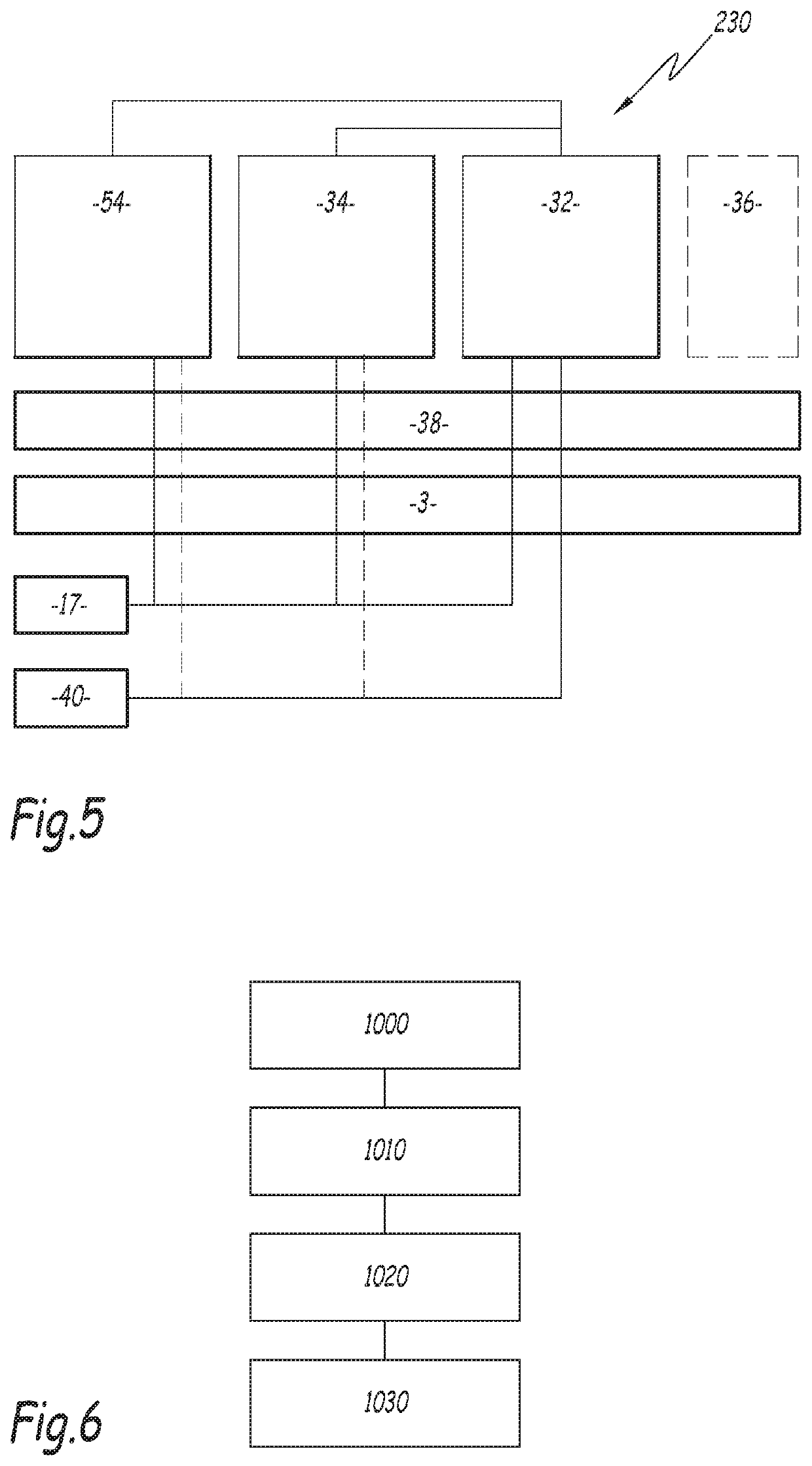
A method including running a virtualization layer on a processor, the virtualization layer being adapted to assign processor time and memory to first and second guest operating systems running on the virtualization layer, wherein the first guest operating system is a real time operating system, obtaining, by the second guest system, information to be displayed on a display, preparing, by the second guest system, a display frame to be sent to the display, reading, by the first guest system, a portion of the display frame, or retrieving, by the first guest system, information about a read portion of the display frame, and determining, by the first guest system, whether the information sent to the second guest system is correctly generated in the display frame.

Description

CROSS-REFERENCE TO RELATED APPLICATIONS[0001]This application claims benefit under 35 USC § 371 of PCT Application No. PCT / EP2018 / 051854 entitled METHOD FOR OPERATING A CONTROL DEVICE, CONTROL DEVICE AND COMPUTER PROGRAM PRODUCT, filed on Jan. 25, 2018 by inventors Michael Peter and Axel Söding Freiherr von Blomberg. PCT Application No. PCT / EP2018 / 051854 claims priority of European Patent Application No. 17 153 995.0, filed on Jan. 31, 2017.FIELD OF THE INVENTION[0002]The present invention concerns a method for operating a control device comprising at least one processor and at least one memory connected to the at least one processor. Further, the present invention relates to a computer program product comprising commands for executing the method.[0003]In addition, the present invention relates to a control device comprising: at least one processor and at least one memory connected to the at least one processor, and a virtualization layer adapted to run on the at least one processor...

Claims


Application Information

Patent Timeline
IPC IPC(8): G06F9/455G06F9/445
CPCG06F9/45558G06F9/44536G06F9/4555B60K35/00G06F3/14G06F9/45533G06F9/4881G06F9/451G06F3/147G09G5/395G09G2358/00G09G2380/10G06F11/1004B60K35/60
Inventor PETER, MICHAELSÖDING-FREIHERR VON BLOMBERG, AXEL
Owner OPENSYNERGY
Learn More