Multi-beam measuring device

a multi-beam, measurement device technology, applied in measurement devices, reradiation using reradiation, electromagnetic wave reradiation, etc., can solve the problems of difficult production, limited distance measurement accuracy, interference crosstalk between individual reception beams, etc., to achieve small angular distance between transmission beams

Pending Publication Date: 2021-04-29
HEXAGON TECH CENT GMBH
View PDF0 Cites 4 Cited by
  • Summary
  • Abstract
  • Description
  • Claims
  • Application Information

AI Technical Summary

Benefits of technology

[0063]Thus, there is the benefit of the achievable small angular distance between transmission beams thanks to the small pitch of the semiconductor laser arrays, e.g. providing for a corresponding high scan point density, while at the same time a seamless scan pattern originating from multiple semiconductor laser arrays is provided despite the fact that additional emitter-free space is required at the axial ends of each of the ...

Problems solved by technology

Furthermore, interfering crosstalks can occur between individual reception beams, wherein a specific reception region corresponding to a first beam detects light of a second beam emitted near the first beam.
As a result, the distance measurement accuracy is limited.
This is difficult to produce, limited in possible spatial resolutio...

Method used


Image

  • Multi-beam measuring device
  • Multi-beam measuring device
  • Multi-beam measuring device

Examples


Embodiment Construction

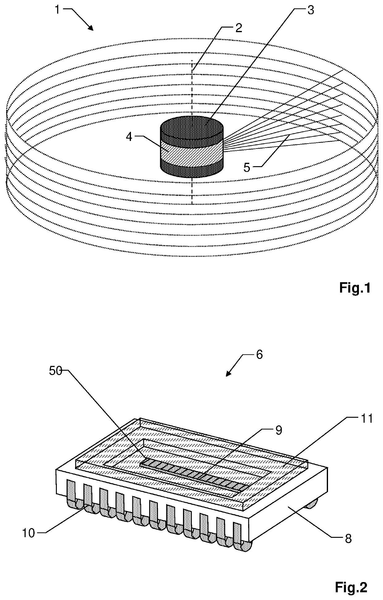
[0137]FIG. 1 shows an outer view of an exemplary measurement device 1, formed with a base and a rotating member (not shown) arranged rotatably on the base about a rotation axis 2 relative to the base. By way of example, the rotating member is enclosed by a protective housing 3, which is fixed to the base and has a circumferential window 4 allowing the transmitted and the returning radiation to pass. Alternatively, the protective housing 3 could also be configured to rotate with the rotating member. In particular, the protective housing may be dustproof and / or waterproof (IP65), wherein the measurement device is configured to compensate for beam deflections of the transmitted and received beams caused by the circumferential window 4.

[0138]The measurement device 1 is configured to generate a plurality of transmission beams for transmitting pulsed distance measuring radiation, wherein different elevations can be scanned by different transmission beams. The elevation here refers to an a...


PUM


Abstract

An absolute distance measuring method and device including a transmission unit having a laser array comprising multiple measurement laser emitters arranged along a laser array axis and a receiver unit having at least one receiver array comprising multiple measurement receivers arranged along a receiver array axis for measuring of an absolute distance based on a respective detected transmission beam and the principle of time-of-flight. The laser array comprises at least a first reference laser emitter and the receiver array comprises at least a first reference receiver. The reference laser emitter and reference receiver define an internal absolute distance reference beam path for calibration of the device with respect to said measuring of absolute distance.

Description

CROSS-REFERENCE TO RELATED APPLICATIONS[0001]This application claims priority to European Patent Application No. 19205917.8, filed on Oct. 29, 2020, European Patent Application No. 20204461.6, filed on Oct. 28, 2020, and European Patent Application No. 20204389.9, filed on Oct. 28, 2020.[0002]The foregoing patent applications are herein incorporated by reference.FIELD OF THE INVENTION[0003]The present invention relates to a multi-beam measurement device for object measuring by means of a plurality of transmission beams.BACKGROUND[0004]Such measurement devices, for example “multibeam laser profilers”, may be used in the fields of mobile mapping, surveying, or autonomous driving. By way of example, the devices are mounted on vehicles, backpacks or drones, e g unmanned ground vehicles (UGVs) or unmanned aerial vehicles (UAVs), to measure the environment or to detect obstacles. Furthermore, the measurement devices may be used in a static assembly, e.g. to monitor certain areas (surveill...

Claims


Application Information

Patent Timeline
IPC IPC(8): G01S17/10G01S7/497G01S17/89G01S7/484G01S7/4865
CPCG01S17/10G01S7/497G01S7/4865G01S7/484G01S17/89G01C15/002G01S7/4815G01S7/4816G01S17/42G01S17/931
Inventor WOHLGENANNT, RAINERDE LANGE, MARTINSEIFERT, BENJAMINBESTLER, SIMONHINDERLING, JÜRG
Owner HEXAGON TECH CENT GMBH
Why Eureka
Try Eureka