System and method for cooling a leading edge of a high speed vehicle

a leading edge and vehicle cooling technology, applied in the direction of heat reducing structures, lighting and heating apparatus, transportation and packaging, etc., can solve the problems of component degradation, failure, and high speed vehicles often experiencing thermal management problems

Active Publication Date: 2021-05-20
GENERAL ELECTRIC CO
View PDF0 Cites 17 Cited by
  • Summary
  • Abstract
  • Description
  • Claims
  • Application Information

AI Technical Summary

Problems solved by technology

High speed vehicles often experience thermal management issues resulting from high heat load experienced during high speed operation, particularly at leading edges where the free air stream impinges on the vehicle.
Unmitigated exposure to such thermal loading can result in component degradation and / or failure.

Method used


Image

  • System and method for cooling a leading edge of a high speed vehicle
  • System and method for cooling a leading edge of a high speed vehicle
  • System and method for cooling a leading edge of a high speed vehicle

Examples


Embodiment Construction

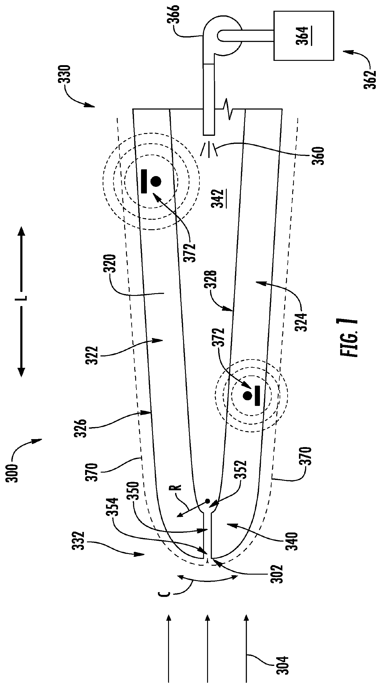
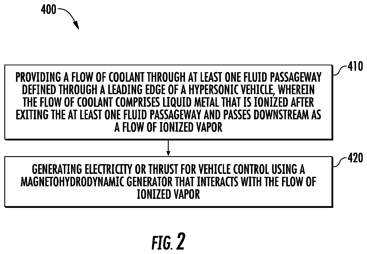
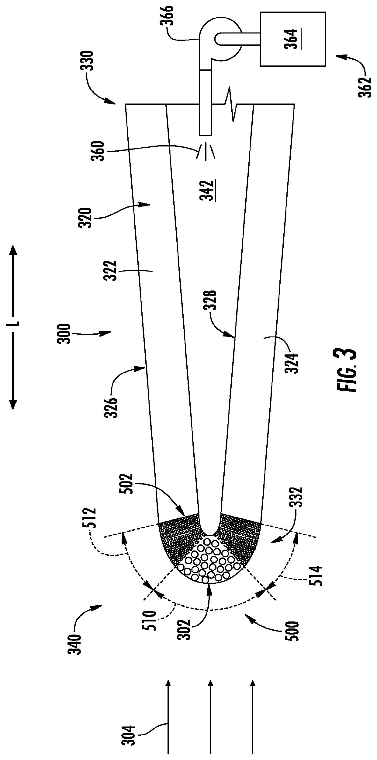
[0017]Reference now will be made in detail to present embodiments of the invention, one or more examples of which are illustrated in the accompanying drawings. The detailed description uses numerical and letter designations to refer to features in the drawings. Like or similar designations in the drawings and description have been used to refer to like or similar parts of the invention.

[0018]The word “exemplary” is used herein to mean “serving as an example, instance, or illustration.” Any implementation described herein as “exemplary” is not necessarily to be construed as preferred or advantageous over other implementations. Moreover, each example is provided by way of explanation of the invention, not limitation of the invention. In fact, it will be apparent to those skilled in the art that various modifications and variations can be made in the present invention without departing from the scope of the invention. For instance, features illustrated or described as part of one embod...


PUM


Abstract

A hypersonic aircraft includes one or more leading edge assemblies that are designed to cool the leading edge of certain portions of the hypersonic aircraft that are exposed to high thermal loads, such as extremely high temperatures and / or thermal gradients. Specifically, the leading edge assemblies may include an outer wall tapered to a leading edge or stagnation point. A coolant supply provides a flow of cooling fluid to a porous tip that is joined to the forward end of the outer wall and defines variable porosity and / or internal barriers to direct a flow of cooling fluid to the regions of the leading edge experiencing the highest thermal loading.

Description

FIELD[0001]The present subject matter relates generally leading edge technologies for use in high speed vehicles, such as hypersonic aircraft.BACKGROUND[0002]High speed vehicles often experience thermal management issues resulting from high heat load experienced during high speed operation, particularly at leading edges where the free air stream impinges on the vehicle. For example, in an application involving hypersonic aircrafts, the leading edges can include the nose, engine cowls, and the leading edges of wings and stabilizers. Particularly when these vehicles are operating in the hypersonic speed range (e.g., Mach 5 or greater), the leading edges may be subjected to very high heat load (e.g., 500-1500 W / cm2) as the incident airflow passes through a bow shock and comes to rest at the vehicle surface, converting the kinetic energy of the gas to internal energy and greatly increasing its temperature. Unmitigated exposure to such thermal loading can result in component degradation ...

Claims


Application Information

Patent Timeline
Patent Type & Authority Applications(United States)
IPC IPC(8): B64C1/38F28F13/00B64C3/36
CPCB64C1/38B64C30/00B64C3/36F28F13/003
Inventor RATHAY, NICHOLAS WILLIAMRUSH, BRIAN MAGANNJOSHI, NARENDRA DIGAMBERSOMMERER, TIMOTHY JOHNNATSUI, GREGORY ALEXANDERBRZEK, BRIAN GENEHOFER, DOUGLAS CARL
Owner GENERAL ELECTRIC CO
Why Eureka
Try Eureka