
Robots working in shifts and shift rotation method therefor

Pending Publication Date: 2021-05-20
ELECTRONICS & TELECOMM RES INST
View PDF0 Cites 0 Cited by
  • Summary
  • Abstract
  • Description
  • Claims
  • Application Information

AI Technical Summary

Benefits of technology

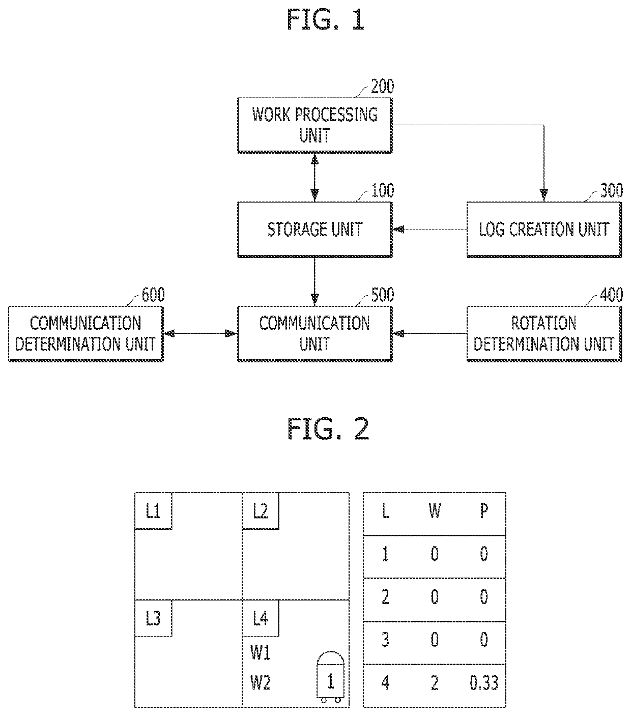
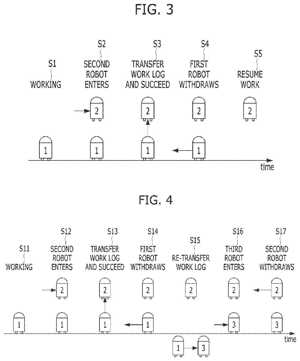
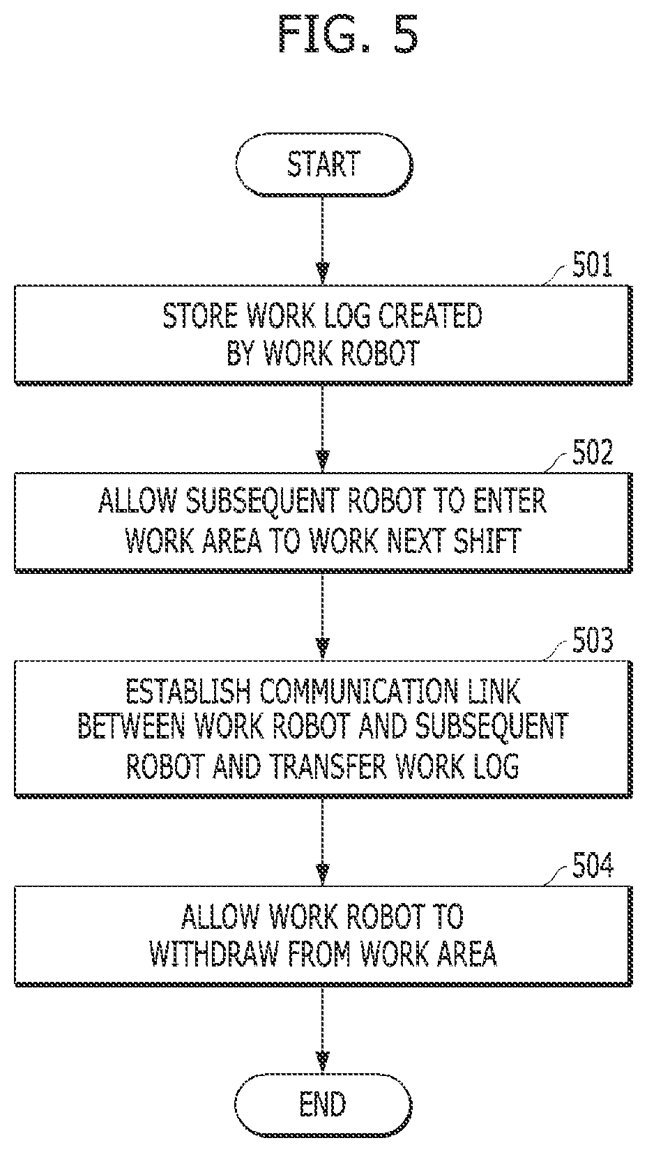
The patent describes a method for transferring information between two robots in a work area. The first robot monitors the environment and can move out of the way to make space for a second robot. The second robot then moves into the work area and communicates with the first robot to receive the information it needs to do its job. The first robot can withdraw from the work area and the second robot takes over, using the information it received from the first robot. The method ensures that the second robot can safely enter the work area and perform its tasks without causing any damage or discomfort to the environment.

Problems solved by technology

In facilities and spaces such as factories, power plants, and the deep sea, it is necessary to alternately allocate and operate multiple robots because one robot cannot perform a continuous task alone due to durability and power issues.
In environments in which robots operate, there are cases in which it is not possible to transfer work logs due to various variables.
In particular, since electronic components of such a robot are highly likely to be damaged due to a harsh environment, a failure to transfer a work log may cause a big problem by affecting work continuity.

Method used


Image

  • Robots working in shifts and shift rotation method therefor
  • Robots working in shifts and shift rotation method therefor
  • Robots working in shifts and shift rotation method therefor

Examples


Embodiment Construction

[0035]Advantages and features of the present invention and implementation methods thereof will be clarified through the following embodiments described in detail with reference to the accompanying drawings. However, the present invention is not limited to embodiments disclosed herein and may be implemented in various different forms. The embodiments are provided for making the disclosure of the prevention invention thorough and for fully conveying the scope of the present invention to those skilled in the art. It is to be noted that the scope of the present invention is defined by the claims. The terminology used herein is for the purpose of describing particular embodiments only and is not intended to be limiting to the invention. As used herein, the singular forms “a,”“an,” and “one” include the plural unless the context clearly indicates otherwise. It will be further understood that the terms “comprises” and / or “comprising,” when used in this specification, specify the presence o...


PUM


Abstract

Provided is a robot working in shifts, the robot including a storage unit configured to store received work plan information including a work position, work information, and workload information, and a work log created and received by a preceding work robot, a work processing unit configured to move to a work area and then work on the basis of plane information when only the work plan information is present in the storage unit, a log creation unit configured to detect workload performed through the work processing unit and work position information regarding a work position to which the robot has moved for work, create a work log including the detected workload and work position information, and store the created work log in the storage unit; a rotation determination unit configured to determine a shift rotation cycle; and a communication unit configured to establish a communication link with a subsequent robot and transfer the work log stored in the storage unit to the subsequent robot when the rotation determination unit determines that a shift rotation time comes and the subsequent robot approaches the work area.

Description

CROSS-REFERENCE TO RELATED APPLICATION[0001]This application claims priority to and the benefit of Korean Patent Application No. 10-2019-0145599, filed on Nov. 14, 2019, the disclosure of which is incorporated herein by reference in its entirety.BACKGROUND1. Field of the Invention[0002]The present invention relates to robots working in shifts and a shift rotation method therefor.2. Discussion of Related Art[0003]In facilities and spaces such as factories, power plants, and the deep sea, it is necessary to alternately allocate and operate multiple robots because one robot cannot perform a continuous task alone due to durability and power issues.[0004]However, in order for multiple robots to have work continuity, it is necessary to transfer a work log to a subsequent robot. In environments in which robots operate, there are cases in which it is not possible to transfer work logs due to various variables.[0005]In particular, since electronic components of such a robot are highly likely...

Claims


Application Information

Patent Timeline
IPC IPC(8): G05B19/4155
CPCG05B19/4155G05B2219/34348G05B2219/40306G06Q10/06315B25J9/1682B25J9/1669B25J9/163B25J9/1628B25J11/00
Inventor KOO, YONG BON
Owner ELECTRONICS & TELECOMM RES INST
Learn More