Check patentability & draft patents in minutes with Patsnap Eureka AI!

Processing Device

Active Publication Date: 2021-05-20
HITACHI ASTEMO LTD
View PDF0 Cites 0 Cited by
  • Summary
  • Abstract
  • Description
  • Claims
  • Application Information

AI Technical Summary

Benefits of technology

The patent makes it easy to see if a certain part of an image has already been downloaded.

Problems solved by technology

Since a camera lens has a distortion characteristic, generated image data includes distortion.
In addition, depending on camera installation conditions, effects such as enlargement, reduction, rotation, and shearing may occur and the generated image data includes even more differences from the actual image.
A storage device for storing image data generally tends to be more costly when an access speed is faster.
However, in an image correction process where the same data is read repeatedly, a low access speed may cause a decrease in a processing speed.

Method used


Image

  • Processing Device
  • Processing Device
  • Processing Device

Examples


embodiment

[0017]Hereinafter, an embodiment of an image processing device is described with reference to FIGS. 1 to 9.

Configuration

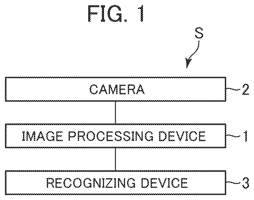
[0018]FIG. 1 is a diagram depicting a configuration of an image processing system S including an image processing device 1. The image processing system S includes the image processing device 1, a camera 2, and a recognizing device 3. The camera 2 outputs an image (hereinafter referred to as “captured image”) acquired by imaging to the image processing device 1. The image processing device 1 executes a distortion correction process on the captured image to generate an image (hereinafter referred to as “distortion-corrected image) obtained by correcting distortion and outputs the distortion-corrected image to the recognizing device 3. The recognizing device 3 executes various applications using the distortion-corrected image. The image processing device 1, the camera 2, and the recognizing device 3 may be connected to each other by wires and may transmit and receive ...

operation example

[0032]An operation example of the image processing device 1 is described with reference to FIG. 7. FIG. 7(a) depicts regions that are included in the high-speed storage unit 145 and on which writing is executed first to fourth. FIG. 7(b) depicts regions that are included in the high-speed storage unit 145 and on which writing is executed thirty fourth to thirty seventh. FIG. 7 (c) depicts values stored in the management table 144. A number indicated in each of grid cells depicted in FIGS. 7 (a) and 7 (b) indicates the number of times that writing is executed when image information is written to the grid cell. The regions enclosed by bold lines in FIG. 7 are regions corresponding to addresses generated by the simple address generating unit 142.

[0033]Since information of the captured image is not stored in the high-speed storage unit 145 before the start of the operation example depicted in FIG. 7, the maximum values among the Y coordinates are zero for all columns of c1 to c128, as i...

first modified example

[0048]It is not a requirement that the number of pixels that can be stored in the high-speed storage unit 145 is in units in which data is read from the low-speed storage unit 13, and the number of pixels that can be stored in the high-speed storage unit 145 may be an integer multiple of the units in which data is read from the low-speed storage unit 13. Moreover, the number of pixels that can be stored in the high-speed storage unit 145 may be any other number of pixels. In addition, the foregoing X direction and Y direction, or column direction and row direction, can be interchanged.


PUM


Abstract

A processing device includes a low-speed storage unit that stores an image extending in a column direction and a row direction, a high-speed storage unit on which reading is executed at a higher speed than the low-speed storage unit and which stores a region corresponding to the entire image in the column direction and a predetermined storage row that is a portion in the row direction of the image, a reading unit that continuously reads the image in the column direction from the high-speed storage unit, and a determining unit that reads the image from the low-speed storage unit and writes the image to the high-speed storage unit. The determining unit determines a row number to be read next in the image based on the minimum or maximum row number in the row direction of the image, stored in the high-speed storage unit for each of targets that are to be processed and are obtained by dividing the column direction into predetermined pixels.

Description

TECHNICAL FIELD[0001]The present invention relates to a processing device.BACKGROUND ART[0002]Since a camera lens has a distortion characteristic, generated image data includes distortion. In addition, depending on camera installation conditions, effects such as enlargement, reduction, rotation, and shearing may occur and the generated image data includes even more differences from the actual image. Furthermore, when a recorded image is reproduced, the reproduced image may include effects such as enlargement, reduction, and shearing depending on installation conditions of a reproducing device. An image processing device, which corrects such differences from the actual image, calculates correspondence relationships between the image before the correction and the image after the correction and reads pixels before the correction or a collection of pixels, which are necessary for pixels of the image after the correction. A storage device for storing image data generally tends to be more...

Claims


Application Information

Patent Timeline
IPC IPC(8): G06T1/60G06T1/20G06F12/0815
CPCG06T1/60G06F12/0815G06T1/20
Inventor UCHIDA, YUSUKEMIZOSOE, HIROKI
Owner HITACHI ASTEMO LTD
Features
  • R&D
  • Intellectual Property
  • Life Sciences
  • Materials
  • Tech Scout
  • Unparalleled Data Quality
  • Higher Quality Content
  • 60% Fewer Hallucinations
Learn More