Sampling Device

Pending Publication Date: 2021-06-24
PHARMA & NUTRACEUTICAL PD PTY LTD
View PDF3 Cites 1 Cited by
  • Summary
  • Abstract
  • Description
  • Claims
  • Application Information

AI Technical Summary

Benefits of technology

[0013]In general terms, the underlining design principle of the present invention is to separate any disturbance the insertion of a sampling device or probe causes to a granule bed from the area targeted for sampling (i.e. the sampling zone) and to capture a sample without forcing or otherwise requiring the particles within the sampling zone to move. In broad terms, this is achieved by introducing an elongate separating member (e.g. in the simplest embodiment resembles a large thin spatula or plate) that, when the device is inserted into the granule bed, separates the granule bed into sampling and non-sampling zones. The sampling side of the separating member (i.e. the side facing towards the sampling zone) is advantageously smooth and free of any protrusions during insertion. Prior to and during insertion, all the mechanical elements necessary for sampling are contained

Problems solved by technology

However, in spite of the well-recognised importance of evaluation of blend homogeneity, there is no industry-wide consensus on how to conduct such tests and currently available sampling devices cannot collect the desired samples without disturbing the granule bed and thus altering the composition of the collected samples.
Supp 458, D.N.J. 1993), these issues remain a problem today in current sampling practices throughout the pharmaceutical industry.
The construction of these thief sampling probes give rise to a number of inherent problems which result in errors and inconsistency when taking samples, including, but not limited to: (i) the diameter of the probe pushes particles during insertion, concentrating fine particles closer to the probe, (ii) the sample entry cavities on the outer sleeve entrap particles (mainly fines) from the above layers and drag them down, thereby contaminating the collected samples, and (iii) problems relating to flow capture such as the need for the particles to flow into the sam

Method used


Image

  • Sampling Device
  • Sampling Device
  • Sampling Device

Examples


Embodiment Construction

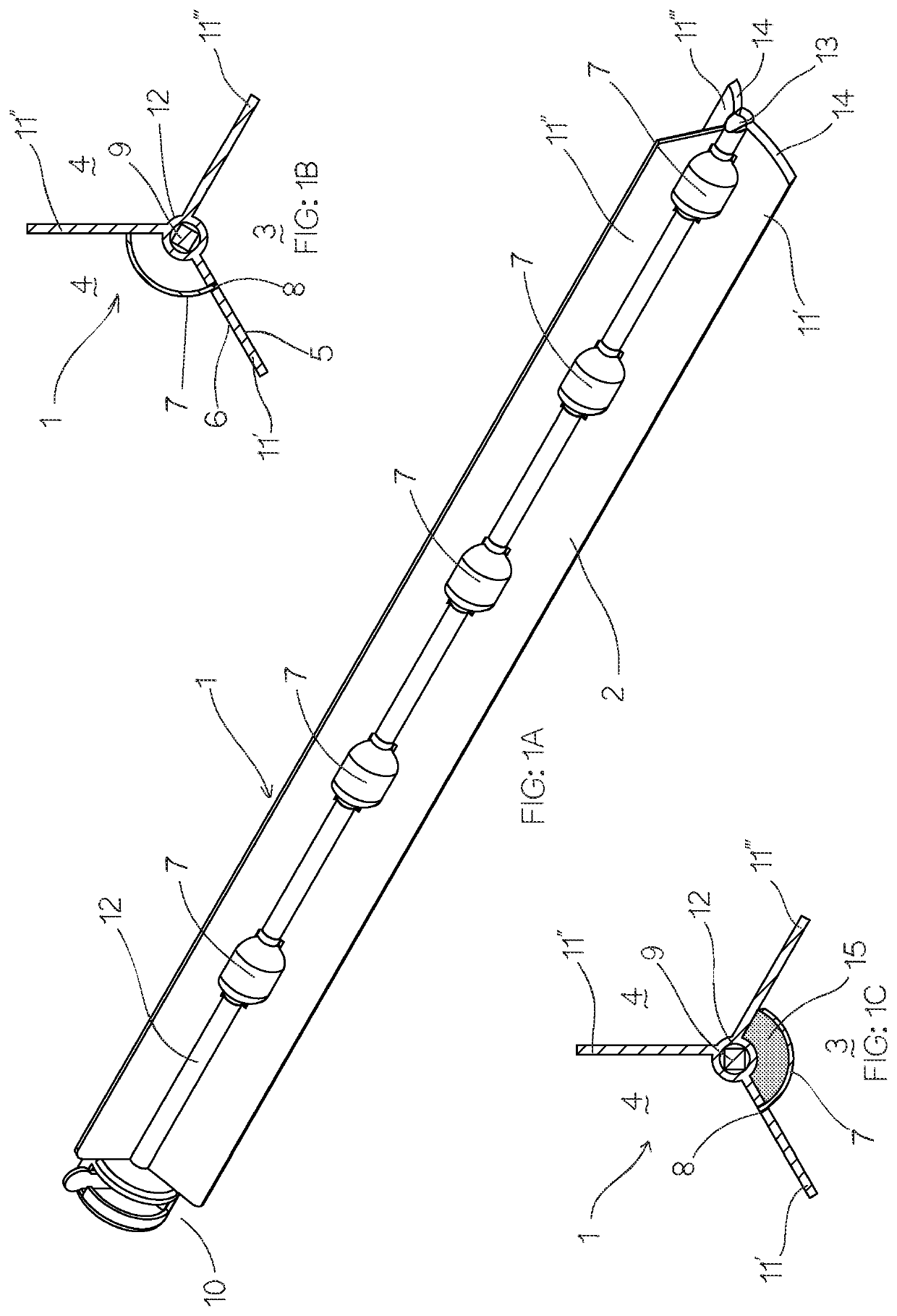
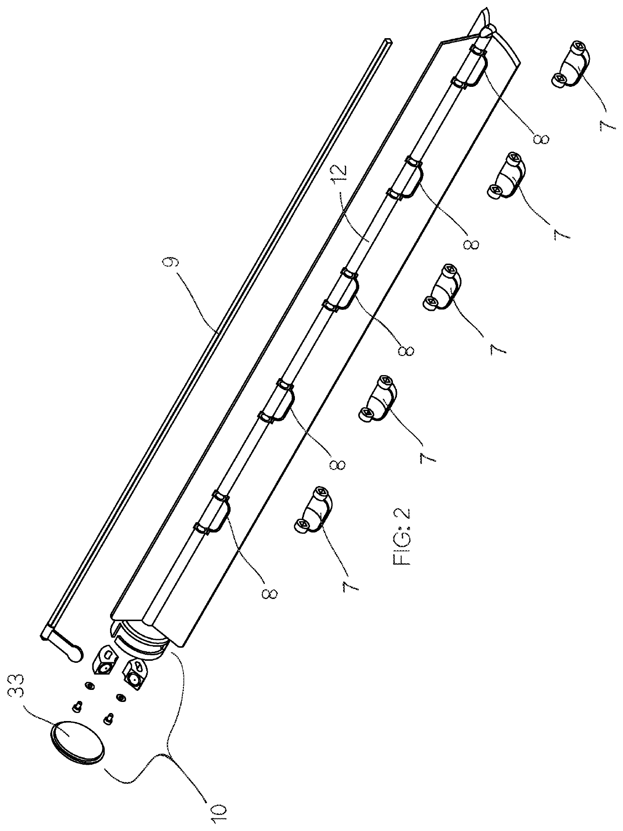
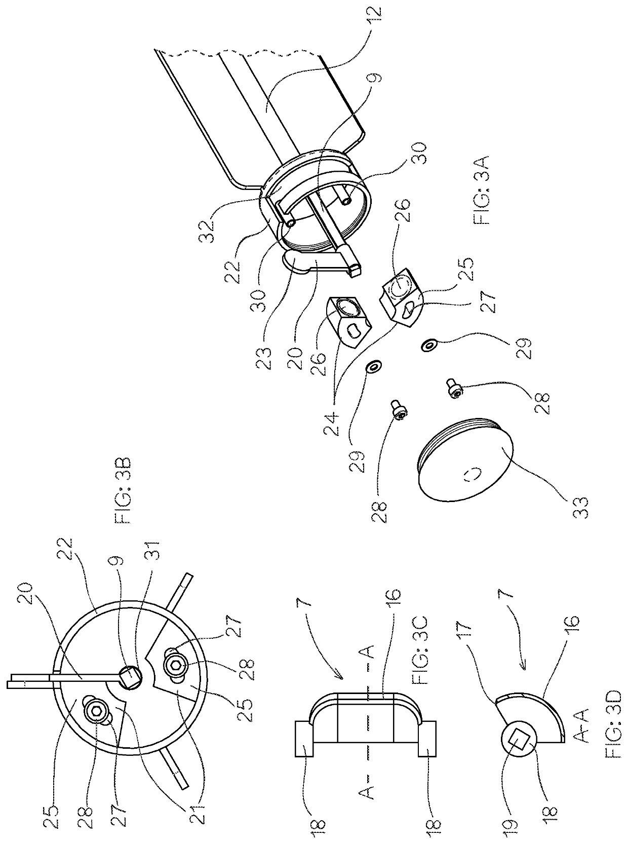
[0123]Referring initially to FIGS. 1A to 1C, the invention provides a sampling device 1 for capturing a sample of particulate material.

[0124]In the illustrated embodiments, the device 1 is adapted for capturing a sample of a predetermined volume of a pharmaceutical powder blend from a reservoir of the particulate material housed within a mixing vessel. For clarity of description and by way of example only, the following description of the drawings is made with specific references to pharmaceutical powders, where it is desired to test the ratios of the various constitute components that form a particular pharmaceutical. However, it will be appreciated by those skilled in the art that the sampling device is not limited to use with pharmaceutical powders but is readily adaptable for use in sampling other forms of blended particulate material where it is desired to accurately test the ratios of the various component materials in a sample against the desired ratios of a particular blende...


PUM


Abstract

This invention relates to a sampling device. The device includes an elongate separating member having a sampling side and a non-sampling side. One or more through openings extend from the sampling side to the non-sampling side of the elongate member. The separating member is adapted for insertion into a reservoir of particulate material so as to define a sampling zone and a non-sampling zone within the reservoir. A shaft is positioned away from the sampling side and operably associated with the separating member, wherein the shaft is selectively rotatable about its longitudinal axis. One or more sample capturing scoops are attached to the shaft so as to be aligned with a respective opening. The or each scoop has a leading edge, a trailing edge and a cavity for receiving a sample of particulate material. The device is configured such that rotation of the shaft about its longitudinal axis causes a corresponding rotation of the or each scoop between a first position and a second position. In the first position, the leading edge of the associated scoop is located within the respective opening such that the opening is effectively closed and the remainder of the scoop projects away from the sampling side such that the sampling side of the separating member is free of protuberances during insertion into the reservoir. In the second position, the scoop is positioned on the sampling side and the leading edge of the associated scoop bears against the sampling side of the elongate member, thereby to enclose the sample of particulate material by the rotation of the scoop towards the second position.

Description

FIELD OF THE INVENTION[0001]The present invention relates to sampling devices. More particularly the invention relates to devices for sampling of particulate materials such as powder blends, especially pharmaceutical blends.[0002]The invention has been developed primarily for use as a powder sampling device for conducting unit dose related volume sampling of free-flowing or cohesive pharmaceutical powder or granule mixtures from mixers, blenders or storage containers and will be described predominantly in this context. However, it will be appreciated that the invention is not limited to this particular field of use, being potentially applicable in a wide variety of applications where samples of particulate materials are required.BACKGROUND OF THE INVENTION[0003]The following discussion of the prior art is intended to facilitate an understanding of the invention and to enable the advantages of it to be more fully understood. It should be appreciated, however, that any reference to pr...

Claims


Application Information

Patent Timeline
IPC IPC(8): G01N1/16B01L3/18G01F11/24G01N33/00
CPCG01N1/16B01L3/18G01N2033/0091G01N33/00G01F11/24G01N1/02B01L3/502715B01L3/502761G01N1/08G01N2001/1006
Inventor PATAKI, ATTILAPATAKI, SEAN KIM
Owner PHARMA & NUTRACEUTICAL PD PTY LTD
Why Eureka
Try Eureka