Expandable fusion device with interdigitating fingers

a fusion device and expandable technology, applied in the field of medical devices and methods, can solve the problems of difficult surgery to install the fusion device in the distracted intervertebral space, difficulties in a surgeon's installation of the fusion device, and the devices and procedures used in the art still suffer several problems, so as to reduce the risk and the effect of surgical complexity

Active Publication Date: 2021-07-01
INTEGRITY IMPLANTS INC
View PDF6 Cites 16 Cited by
  • Summary
  • Abstract
  • Description
  • Claims
  • Application Information

AI Technical Summary

Benefits of technology

[0009]Expandable spinal fusion devices, systems, and methods of using them are provided, and they can be inserted in a subject in a collapsed state through a small surgical corridor, and the expand cephalocaudal only, transverse only, or in both directions, in which direction of expansion can also be obtained independently, if desired, after the insertion. These inventions are valuable in reducing risk and surgical complexity, allowing for an on-the-fly selection of a desirable width footprint, a desired control of height expansion through a gradual cephalocaudal expansion, and a desired control of the alignment of the adjacent vertebral bodies. Devices, systems, and methods are also offered to provide a desired control of the contact area desired between the device and the upper and lower vertebral endplates achieved, for example, using an interdigitated endplate system.
[0014]It should be appreciated that the spacer system can have a single spacer, or a plurality of spacers. In some embodiments, for example, the spacer system can have any configuration desired, for example, as it can have a pair of spacer of equal or different width and / or length. In some embodiments, a pair of spacers can be inserted independently or as part of a combined spacer unit. Such a combined spacer unit can be forked, for example, and it can be removable as a tool after establishing the desired spacing in vivo, or it can be left in place in the subject during the procedure as an implant. One of skill will appreciate the versatility in selecting a spacer size on-the-fly, to obtain a desired width, for example, as the desired amount of expansion can vary, and can change during a procedure. Moreover, the skilled artisan will also highly appreciate that the expansion of the device using the drive system operates independent of the expansion of the device using the spacer system, offering an improved versatility in the operating room.
[0020]Methods of fusing intervertebral spaces are also provided. In some embodiments, a method of fusing an intervertebral space of a subject can include inserting any device taught herein into an intervertebral space of the subject with an inserter tool and performing a cephalocaudal expansion and a transverse expansion of the device by (i) actuating the drive system and (ii) inserting the spacer system into the device, the actuating and inserting performed independently and in separate steps. One of skill will appreciate that the performing of the expansion using the drive system operates can be independent of the expansion using the spacer system, which provides a great deal of needed versatility and control in the operating room.
[0024]Likewise, devices that expand laterally while providing a substantial increase in the area that contacts vertebral endplates are provided. In some embodiments, a laterally expandable fusion device can include an upper endplate assembly having a first endplate with a first plurality of protrusions and a second endplate with a second plurality of protrusions; and a lower endplate assembly having a third endplate with a third plurality of protrusions and a fourth endplate with a fourth plurality of protrusions. In some embodiments, the first plurality of protrusions are interdigitated with the second plurality of protrusions to telescope upon the lateral expansion and provide a substantially increased surface area for contact with an upper vertebral endplate in an intervertebral space; the third plurality of protrusions are interdigitated with the fourth plurality of protrusions to telescope upon the lateral expansion and provide a substantially increased surface area for contact with an lower vertebral endplate in an intervertebral space; and, each of the first endplate, second endplate, third endplate, and fourth endplate have a plurality of receptacles for (i) receiving each of the respective plurality of protrusions upon a collapse of the device; and, (ii) releasing each of the respective plurality of protrusions upon a collapse of the device. In such embodiments, each protrusion on one endplate can have a mating surface, on the opposing endplate, such as recess, groove, channel, or port, for example, to mate with, or be received, on the opposing or adjacent end-plate. In some embodiments, the first plurality of protrusions and the second plurality of protrusions slidably translate with a tongue-in-groove configuration to provide additional rigidity to the upper endplate assembly upon the lateral expansion; and, the third plurality of protrusions and the fourth plurality of protrusions slidably translate with a tongue-in-groove configuration to provide additional rigidity to the lower endplate assembly upon the lateral expansion.

Problems solved by technology

However, there are challenges associated with the known conventional fusion devices and methodologies.
This difference in height may make it difficult for a surgeon to install the fusion device in the distracted intervertebral space.
Unfortunately, the devices and procedures used in the art still suffer several problems, including those discussed above.

Method used


Image

  • Expandable fusion device with interdigitating fingers
  • Expandable fusion device with interdigitating fingers
  • Expandable fusion device with interdigitating fingers

Examples


Embodiment Construction

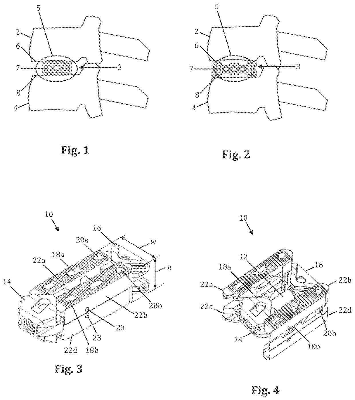
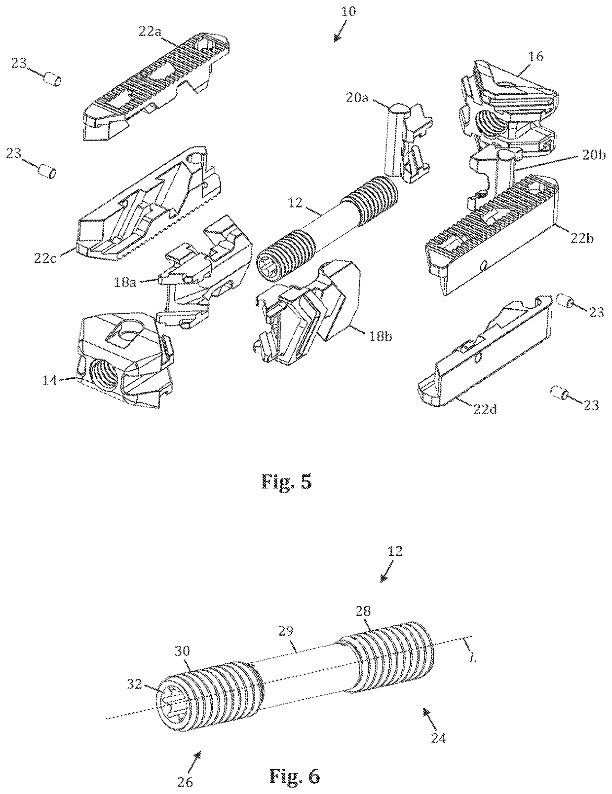
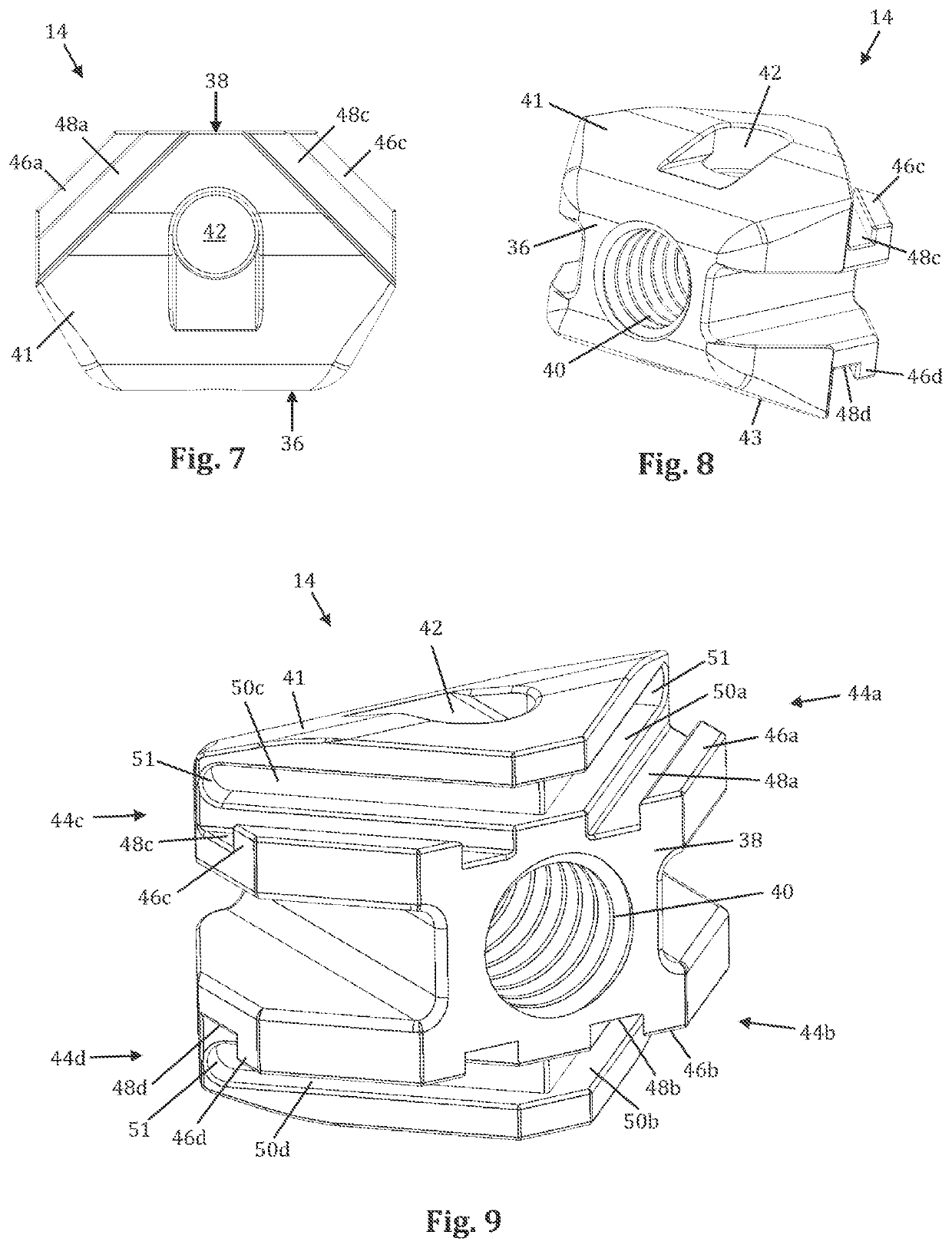
[0136]Expandable spinal fusion devices, systems, and methods of using them are provided and reduce surgical complexity and risk through the use of a minimum to minimal, or perhaps no, intervertebral distraction and use of a small surgical corridor. The devices, systems, and methods allow for a desired width control in the expansion of the device through a variable transverse expansion system in a single device which provides for an on-the-fly selection of a desirable footprint, which can be a larger, or perhaps biased, footprint for achieving a desired alignment, or perhaps for avoiding subsidence of the device during use. They also allow for a desired control of height expansion through a gradual cephalocaudal expansion of the device, gradually increased at a desired amount and speed via a drive system, to obtain a desirable intervertebral height and / or pressure, for controllably decompressing the neural elements and reaching the desired the intervertebral height with increased saf...


PUM


Abstract

Expandable spinal fusion devices, systems, and methods of using them are provided, and they can be inserted in a subject in a collapsed state through a small surgical corridor, and the expand cephalocaudal only, transverse only, or in both directions, in which direction of expansion can also be obtained independently, if desired, after the insertion. These inventions are valuable in reducing risk and surgical complexity, allowing for an on-the-fly selection of a desirable width footprint, a desired control of height expansion through a gradual cephalocaudal expansion, and a desired control of the alignment of the adjacent vertebral bodies. Devices, systems, and methods are also offered to provide a desired control of the contact area desired between the device and the upper and lower vertebral endplates achieved, for example, using an interdigitated endplate system.

Description

CROSS REFERENCES TO RELATED APPLICATIONS[0001]This is a continuation application of U.S. application Ser. No. 16 / 290,428, filed Mar. 1, 2019, which claims priority to U.S. Provisional Application No. 62 / 637,306, filed Mar. 1, 2018, each of which is hereby incorporated herein by reference in its entirety.BACKGROUNDField of the Invention[0002]The teachings herein are directed generally to medical devices and methods, including devices and methods for promoting an intervertebral fusion, such as devices that can be inserted in a subject in a collapsed state through a small surgical corridor, and the expand cephalocaudal only, transverse only, or in both directions, in which direction of expansion can also be obtained independently, if desired, after the insertion.Description of the Related Art[0003]The teachings provided herein include methods, devices, and systems for performing a spinal implant procedure on a subject. A spinal fusion is typically employed to eliminate pain caused by t...

Claims


Application Information

Patent Timeline
Patent Type & Authority Applications(United States)
IPC IPC(8): A61F2/44
CPCA61F2/447A61F2002/30579A61F2250/0009A61F2/4425A61F2002/30537A61F2002/30538A61F2/4455A61F2002/30266A61F2002/30331A61F2002/30398A61F2002/30405A61F2002/30476A61F2002/30482A61F2002/30507A61F2002/30528A61F2002/30593A61F2002/30624A61F2002/30383A61F2/4611A61F2002/30387A61F2002/30401A61F2002/30411A61F2002/30545A61F2002/3055A61F2002/30556A61F2002/443
Inventor SHOSHTAEV, EUGENE
Owner INTEGRITY IMPLANTS INC
Why Eureka
Try Eureka