Patient lift device and method

a technology for lifting devices and patients, applied in hospital equipment, medical science, nursing beds, etc., can solve problems such as insufficient strength for help, caregiver injuries, and difficulty in adjusting to the new position of patients, and achieve the effect of improving the mobility of patients and reducing the difficulty of adjusting to the new position

Inactive Publication Date: 2021-07-01
HANDICARE CANADA LTD
View PDF0 Cites 0 Cited by
  • Summary
  • Abstract
  • Description
  • Claims
  • Application Information

AI Technical Summary

Benefits of technology

The invention provides a patient lift device that can automatically lift and lower a patient using a motor, a lifting element, and a harness for holding the patient. The device also includes a load sensor and a controller for controlling the motor based on the sensed load on the device. This allows the device to automatically adjust the lifting force to the patient's needs. Additionally, the invention also provides a feature for identifying and addressing any imbalance in the harness or carry bar that may affect the stability of the patient lift. Overall, the invention improves the safety and efficiency of patient lifting and lowering procedures.

Problems solved by technology

However, sometimes, such patients may be too heavy to lift, or the manual lifting can result in injuries to caregivers, or the attendant may not have enough strength to help the patient move without a mechanical assistive device such as a personal lift.
This issue can be especially acute for disabled patients who have reduced mobility but otherwise normal bodily functions.
Getting up and going to the bathroom to use the toilet or have a bath, for example, can be difficult or impossible for such patients.

Method used


Image

  • Patient lift device and method
  • Patient lift device and method
  • Patient lift device and method

Examples


Embodiment Construction

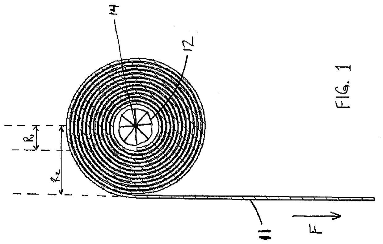
[0016]In a typical lift, the spool winds the strap in a spiral configuration. In other words, starting from full extension, as the spool winds the strap to lift the patient, the strap is being wound on top of itself, with the diameter of the wound portion of the strap thus becoming progressively thicker as the patient is lifted further. This configuration is shown in FIG. 1, which is a cross-sectional view of a strap 11 wound on a spool 12 having a cross-sectional centre point 14. R1 and R2 are thicknesses of the spool and wound strap at different points, and are shown as perpendicular to the portion of the strap extending down to the patient.

[0017]The present inventors have noted that this configuration has certain disadvantages. First, the winding of the strap takes up a lot of space. In order for the strap to have adequate strength to lift and lower patients repeatedly, it has to be both wide and thick, and at the same time has to have a minimum strap length to accommodate liftin...


PUM


Abstract

A patient lift for lifting and lowering a patient. Cable or rope may be used as the lifting element. The spool winds the lifting element in successive adjacent winds. The operator lifts the patient by pushing up on the carry bar, patient or lifting element, and lowers the patient by pushing down on such elements. The lift includes automatic loading and unloading for transition on or off the bed.

Description

FIELD OF THE INVENTION[0001]This invention relates generally to the field of mobility devices, and more particularly, to personal lift devices of the type that may be used to raise or lower a physically disabled person for the purpose of moving that person.BACKGROUND OF THE INVENTION[0002]Personal lift or patient lift devices have been known and used in the past to assist with the mobility of otherwise immobilized or mobility-limited patients. An attendant may help a physically disabled patient who may have suffered a traumatic injury, stroke, or some other illness or condition, and who is unable to move about without assistance. However, sometimes, such patients may be too heavy to lift, or the manual lifting can result in injuries to caregivers, or the attendant may not have enough strength to help the patient move without a mechanical assistive device such as a personal lift. This issue can be especially acute for disabled patients who have reduced mobility but otherwise normal b...

Claims


Application Information

Patent Timeline
IPC IPC(8): A61G7/10
CPCA61G7/1015A61G7/1051A61G7/1065
Inventor ROBLIN, FRANCOISABBASI, HABIBPABBI, VIII, AKASHMORBI, ALIASGARBERANEK, RICHARDTHAKAR, ROHANNIKUMBH, I, SAHIL
Owner HANDICARE CANADA LTD
Why Eureka
Try Eureka