Eureka AIR delivers breakthrough ideas for toughest innovation challenges, trusted by R&D personnel around the world.

Assembly, more particularly turbomachine, comprising a shaft seal device

Pending Publication Date: 2021-07-01
SIEMENS ENERGY GLOBAL GMBH & CO KG +1
View PDF1 Cites 0 Cited by
  • Summary
  • Abstract
  • Description
  • Claims
  • Application Information

AI Technical Summary

Benefits of technology

The invention is a shaft seal device for turbomachines that prevents leakage with low operating costs. The device uses a ferrofluid shaft seal and an additional shaft seal with a pressure sink to achieve high operating reliability, especially for high maximum pressures. The ferrofluid shaft seal is magnetized by a permanent magnet, making it independent of auxiliary energy supplies. A ferrofluid storage container is connected to lines for supplying and discharging the ferrofluid. This compensates for losses and allows for conditioning of the ferrofluid, such as cooling and reversing contaminants. Filtering, separation, cooling, and pumps are attached to the container for contaminant control and supply pressure.

Problems solved by technology

Assemblies of this type are comparatively costly and are therefore frequently not economically successful.
The replenishment of suitable barrier fluid is complicated and costly and is therefore not desired by the customer or is to be kept at a minimum.
One disadvantage of the ferrofluid seal is, however, that the pressure differences occurring in turbomachines are regularly too high.

Method used


Image

  • Assembly, more particularly turbomachine, comprising a shaft seal device
  • Assembly, more particularly turbomachine, comprising a shaft seal device
  • Assembly, more particularly turbomachine, comprising a shaft seal device

Examples


Embodiment Construction

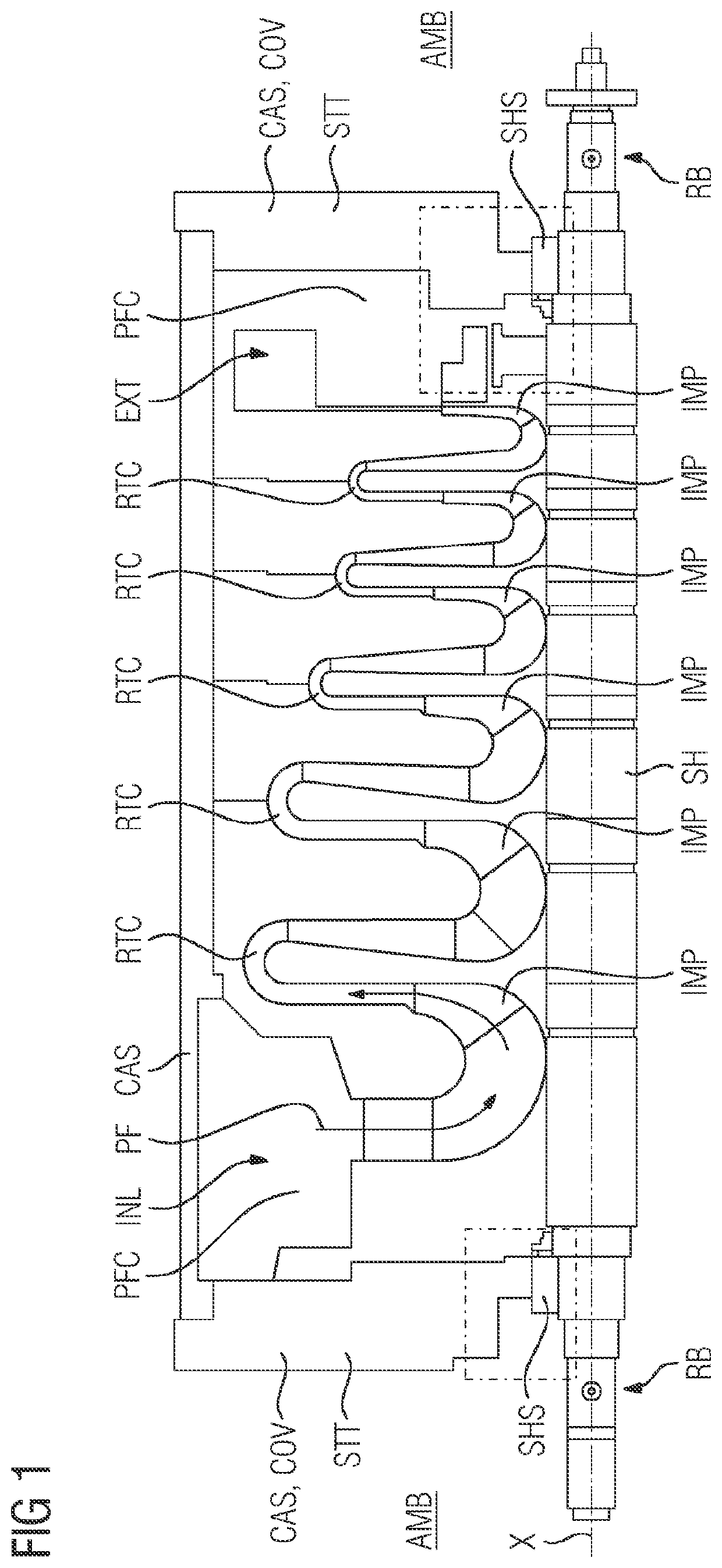
[0015]FIG. 1 shows a schematic illustration of a longitudinal section through a turbomachine TM. The turbomachine TM is designed as an assembly AR according to the invention and comprises a shaft SH, which extends along an axis X. A shaft seal device SHS for sealing an annular gap GP between the shaft SH and a stator STT is provided, in order to seal a process fluid chamber PFC relative to the environment AMB against an escape of process fluid PF. In the practical case, the stator STT is part of a housing CAS or a pressure vessel which maintains the elevated pressure relative to the environment AMB of the process fluid PF in the interior. The housing CAS has a cover COV axially on each side, which is a constituent part of the housing CAS or the stator STT. In principle, terms such as axial, radial, tangential or direction of the environment are based on the axis X of the shaft SH. The turbomachine TM of FIG. 1 is formed as a turbo compressor of radial design. In the interior of the ...


PUM


Abstract

An assembly, more particularly a turbomachine, includes a shaft, which extends along an axis, a shaft seal device for sealing an annular gap between the shaft and a stator in order to seal a process fluid chamber in relation to the environment. The shaft seal device has a ferrofluid shaft seal. At the process fluid chamber, the shaft seal device includes, in addition to the ferrofluid shaft seal, an additional shaft seal. The ferrofluid shaft seal is arranged at the annular gap axially between the first shaft seal and the environment. A pressure sink is provided at the annular gap axially between the additional shaft seal and the ferrofluid shaft seal.

Description

CROSS REFERENCE TO RELATED APPLICATIONS[0001]This application is the US National Stage of International Application No. PCT / EP2019 / 060876 filed 29 Apr. 2019, and claims the benefit thereof. The International Application claims the benefit of European Application No. EP18175111 filed 30 May 2018. All of the applications are incorporated by reference herein in their entirety.FIELD OF INVENTION[0002]The invention relates to an assembly, more particularly a turbomachine, comprising—a shaft, which extends along an axis,—a shaft seal device for sealing an annular gap between the shaft and a stator in order to seal a process fluid chamber in relation to the environment,—wherein the shaft seal device has a ferrofluid shaft seal, wherein, at the process fluid chamber, the shaft seal device comprises an additional shaft seal in addition to the ferrofluid shaft seal,—wherein the ferrofluid shaft seal is arranged at the annular gap axially between the first shaft seal and the environment, where...

Claims


Application Information

Patent Timeline
IPC IPC(8): F16J15/43F16J15/447F01D11/04
CPCF16J15/43F05D2240/55F01D11/04F16J15/447F16J15/004F16J15/44
Inventor GAUSMANN, RAINER
Owner SIEMENS ENERGY GLOBAL GMBH & CO KG
Why Eureka
Eureka Blog
Learn More