Multilayer body and method of manufacturing the same
a multi-layer body and body technology, applied in the field of multi-layer bodies, can solve the problems of increasing reducing and breaking the connection portion, so as to improve the connection strength reduce the size of the multi-layer body
- Summary
- Abstract
- Description
- Claims
- Application Information
AI Technical Summary
Benefits of technology
Problems solved by technology
Method used
Image
Examples
first preferred embodiment
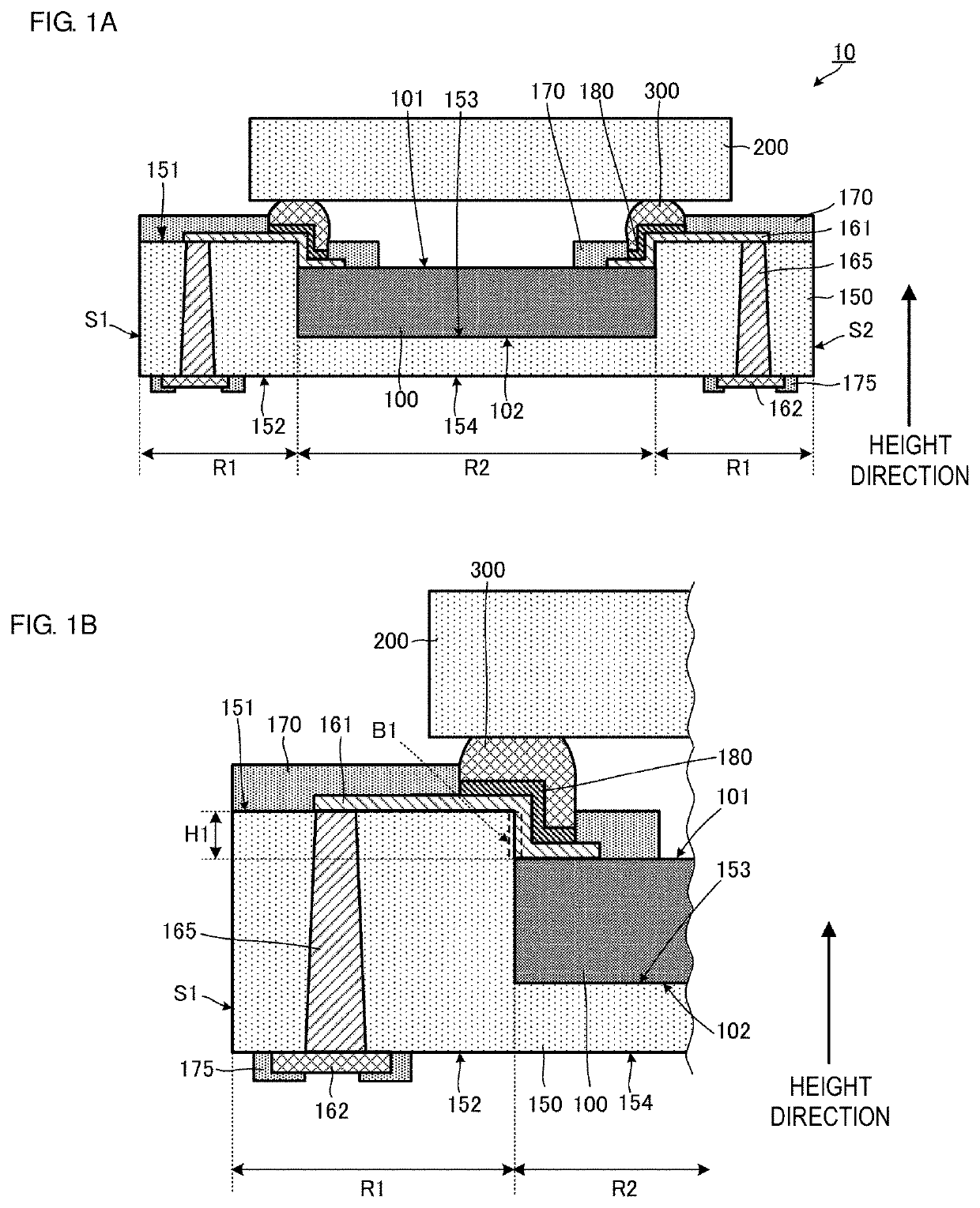
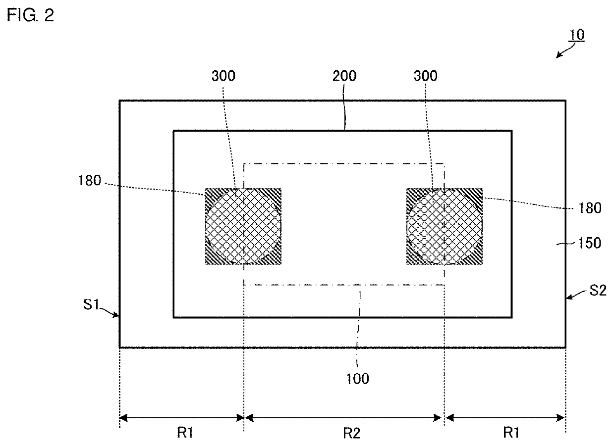
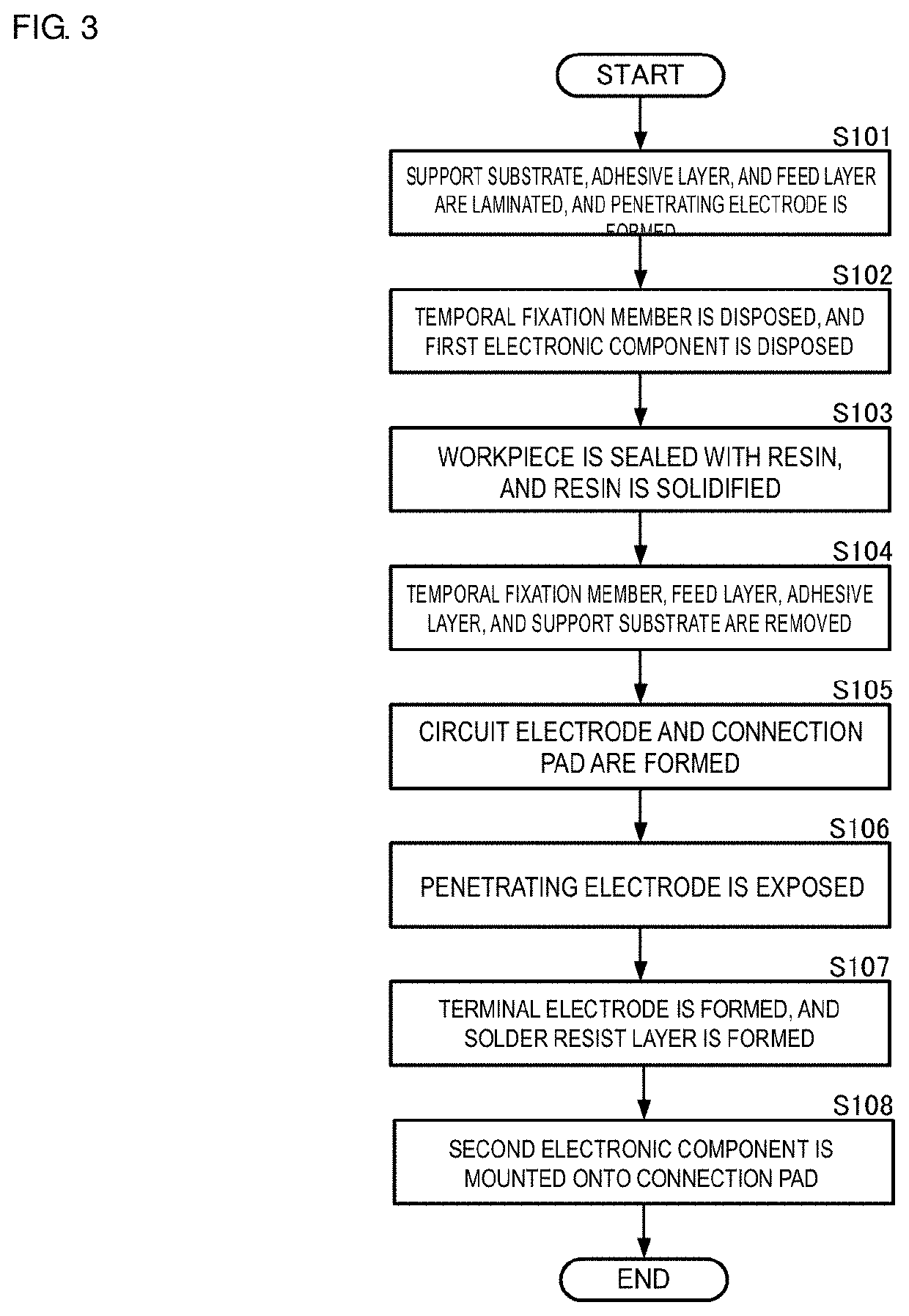
[0031]A multilayer body according to a first preferred embodiment of the present invention will be described with reference to the drawings. FIG. 1A is a cross-sectional side view illustrating a configuration of a multilayer body 10 according to the first preferred embodiment of the present invention, and FIG. 1B is an enlarged cross-sectional side view illustrating a portion of the multilayer body 10 of FIG. 1A. FIG. 2 is a plan view illustrating the multilayer body 10 according to the first preferred embodiment of the present invention when an outer surface thereof is viewed. FIG. 3 is a flow chart illustrating a method of manufacturing the multilayer body 10 according to the first preferred embodiment of the present invention. FIGS. 4A to 4D are cross-sectional side views illustrating the method of manufacturing the multilayer body 10 according to the first preferred embodiment of the present invention. FIGS. 5A to 5C are cross-sectional side views illustrating the method of manu...
second preferred embodiment
[0062]Next, a multilayer body according to a second preferred embodiment of the present invention will be described with reference to the drawings. FIG. 6A is a cross-sectional side view illustrating a configuration of a multilayer body 10A according to the second preferred embodiment of the present invention, and FIG. 6B is an enlarged cross-sectional side view illustrating a portion of the multilayer body 10A of FIG. 6A. FIG. 7 is a flow chart illustrating a non-limiting example of a method of manufacturing the multilayer body 10A. FIGS. 8A to 8D are cross-sectional side views illustrating the method of manufacturing the multilayer body 10A according to the second preferred embodiment of the present invention. FIGS. 9A to 9E are cross-sectional side views illustrating the method of manufacturing the multilayer body 10A according to the second preferred embodiment of the present invention. In the drawings, the relationship between vertical and horizontal dimensions may be exaggerat...
third preferred embodiment
[0087]Next, a multilayer body according to a third preferred embodiment of the present invention will be described with reference to the drawings. FIG. 10 is a cross-sectional side view illustrating a configuration of a multilayer body 10B according to the third preferred embodiment of the present invention. In FIG. 10, the relationship between vertical and horizontal dimensions is exaggerated and does not always reflect actual dimensions.
[0088]As illustrated in FIG. 10, the multilayer body 10B of the third preferred embodiment is different from the multilayer body 10 of the first preferred embodiment in that the multilayer body 10B includes resin films 190 and connection electrodes 195 and in that circuit electrodes 161B and connection pads 180B are shaped differently. Other basic configurations of the multilayer body 10B are the same as or similar to those of the multilayer body 10, and duplicated descriptions will be omitted.
[0089]As illustrated in FIG. 10, the multilayer body 10...
PUM
 Abstract
Description
Claims
Application Information
 - R&D
- Intellectual Property
- Life Sciences
- Materials
- Tech Scout
- Unparalleled Data Quality
- Higher Quality Content
- 60% Fewer Hallucinations
Browse by: Latest US Patents, China's latest patents, Technical Efficacy Thesaurus, Application Domain, Technology Topic, Popular Technical Reports.
© 2025 PatSnap. All rights reserved.Legal|Privacy policy|Modern Slavery Act Transparency Statement|Sitemap|About US| Contact US: help@patsnap.com


