Eureka AIR delivers breakthrough ideas for toughest innovation challenges, trusted by R&D personnel around the world.

Power supply apparatus for stabilizing power supply capability of auxiliary winding provided in transformer

Pending Publication Date: 2021-07-08
CANON KK
View PDF2 Cites 3 Cited by
  • Summary
  • Abstract
  • Description
  • Claims
  • Application Information

AI Technical Summary

Benefits of technology

The present invention is a power supply apparatus that includes a rectifier circuit, a smoothing circuit, a protection circuit, a short-circuiting circuit, a transformer, a delay circuit, a switching element, and a rectifying and smoothing circuit. The technical effects of the invention include an effective protection against inrush current, a short-circuiting function, and precise voltage control. These features make the power supply apparatus suitable for a wide range of applications, especially in situations where reliability and accuracy are important.

Problems solved by technology

Therefore, when a secondary side load is light, the power supply capability of the auxiliary winding is insufficient, and it is impossible to stably drive the primary side load connected to the auxiliary winding.
However, this will likely introduce an increase in the number of parts and an increase in the cost of the power supply apparatus.

Method used


Image

  • Power supply apparatus for stabilizing power supply capability of auxiliary winding provided in transformer
  • Power supply apparatus for stabilizing power supply capability of auxiliary winding provided in transformer
  • Power supply apparatus for stabilizing power supply capability of auxiliary winding provided in transformer

Examples


first embodiment

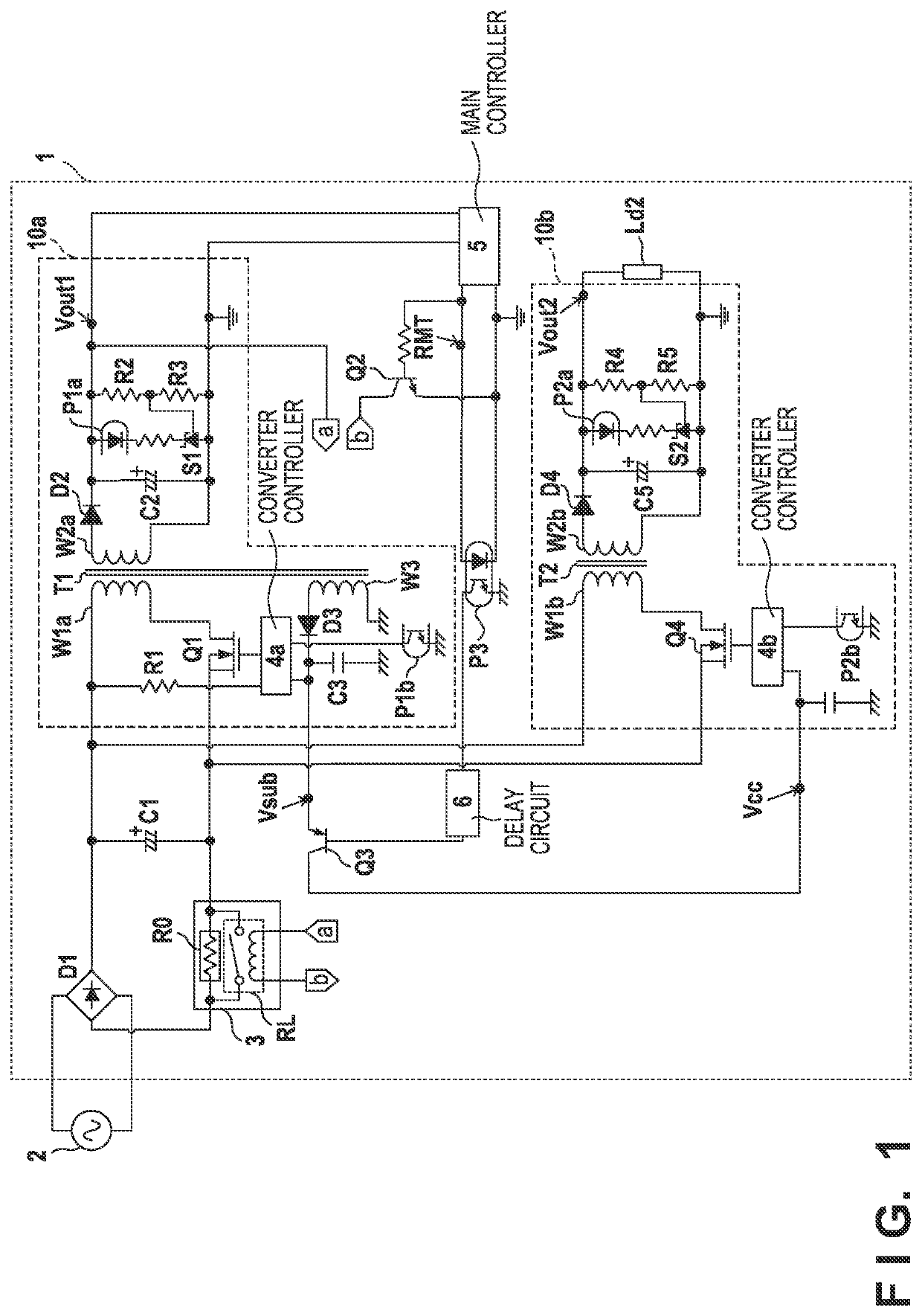
[0014]As shown in FIG. 1, a power supply apparatus 1 is an AC / DC converter for converting an alternating current voltage supplied from a commercial power supply 2 to a direct current voltage and outputting the result. The power supply apparatus 1 includes a first converter 10a and a second converter 10b. The power supply apparatus 1 may be employed, for example, as a power supply for supplying electric power to an image forming apparatus. An electric device such as an image forming apparatus has a normal power mode in which power consumption is large as in a state in which the device is operating, and a power saving mode in which the device is not operating and a part of the power supply is stopped and the power consumption is smaller than that in the normal power mode. Therefore, the first converter 10a may function as a sub power supply that operates in both power modes. The second converter 10b may be stopped in the power saving mode and function as a main power supply that opera...

second embodiment

[0041]In the first embodiment, in order to operate the second converter 10b, the operation start signal RMT is an external signal from the main controller 5 was required. In the second embodiment, the operation start signal RMT for operating the second converter 10b is omitted. Incidentally, the first converter 10a need not be a sub power supply. The second converter 10b need not be a main power supply.

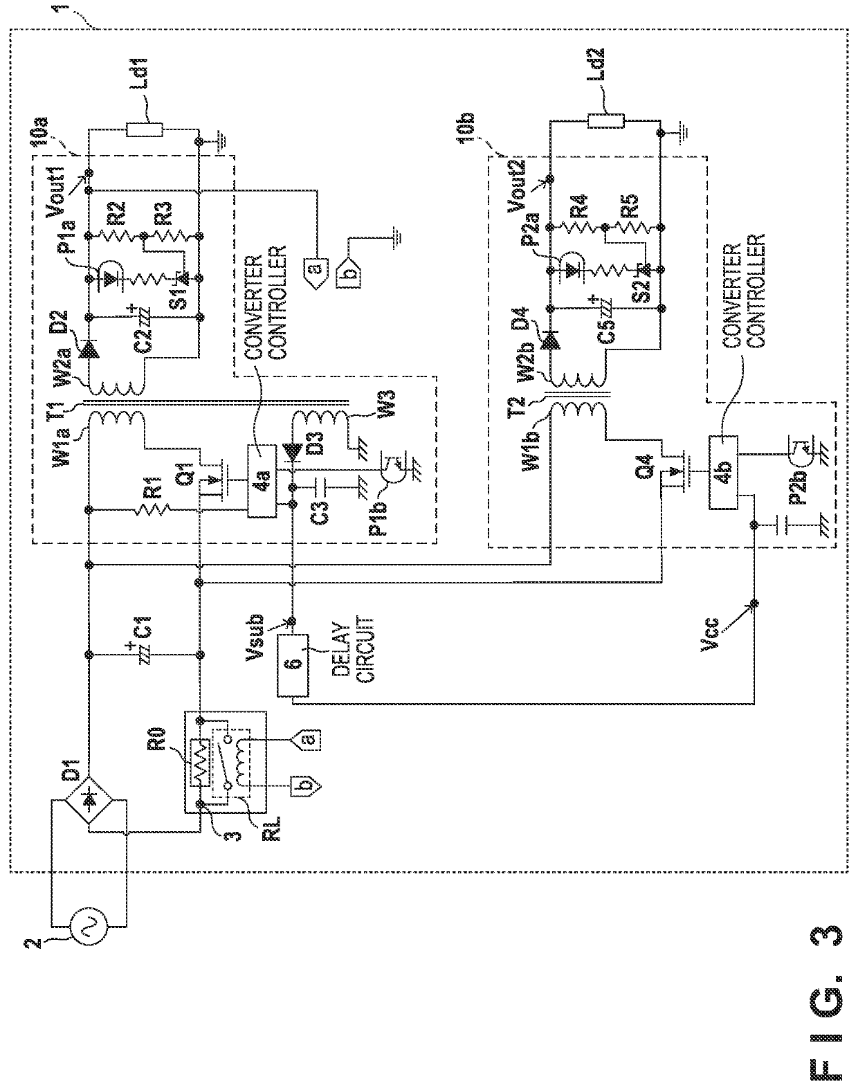
[0042]FIG. 3 shows the power supply apparatus 1 of the second embodiment. Of the circuit configuration shown in FIG. 3, the same reference numerals are given to the circuit configuration already described in FIG. 1, and the description thereof is omitted.

[0043]As shown in FIG. 3, a load Ld1 is connected to the first converter 10a. Further, in the power supply apparatus 1, the main controller 5 and the photocoupler P3 are not provided. Further, to the relay RL, the output voltage Vout1 is supplied directly. That is, the load Ld1 and the relay RL are connected in parallel to the first c...

third embodiment

[0046]In the first embodiment and the second embodiment, the load of the auxiliary winding W3 was the converter controllers 4a and 4b. As shown in FIG. 5, a PFC controller 51 is used as a load of the auxiliary winding W3 in the third embodiment. In the third embodiment, the same reference numerals are assigned to the same items as those in the first and second embodiments, and a description thereof is omitted.

[0047]A PFC circuit 50 is a power factor correction circuit. A capacitor C6 for rectifying the pulsating current output from the diode bridge D1 is provided in the front stage of the PFC circuit 50. The PFC circuit 50 has a booster circuit composed of a coil L1, a diode D5, and a switching element Q5. One end of the coil L1 is connected to one end of the capacitor C6. The other end of the coil L1 is connected to the anode of the diode D5 and the drain of the switching element Q5. The cathode of the diode D5 is connected to one end of a resistor R6 and one end of the capacitor C...


PUM


Abstract

A protection circuit protects a rectifier circuit from an inrush current inputted to a smoothing circuit. A short-circuiting circuit does not short the protection circuit while an inrush current may occur, and shorts it while an inrush current does not occur. A transformer has a primary winding, a secondary winding and an auxiliary winding. A delay circuit delays a timing at which an operation of a load connected to the auxiliary winding is started with respect to a timing at which an operation of the short-circuiting circuit is started. A rectifying and smoothing circuit generates an output voltage by rectifying and smoothing the secondary side voltage. The short-circuiting circuit is driven by the output voltage.

Description

BACKGROUND OF THE INVENTIONField of the Invention[0001]The present invention relates to a power supply apparatus for stabilizing a power supply capability of an auxiliary winding provided in a transformer.Description of the Related Art[0002]Generally, a power supply apparatus converts an input voltage to an output voltage by a transformer. There are also transformers with an auxiliary winding, in addition to a primary winding and secondary winding, among the transformers used in power supply apparatuses. Electric power generated by the auxiliary winding may be used to drive a load arranged on a primary side of the transformer (Japanese Patent Laid-Open No. 11-0032480 and US-2018-0358889).[0003]The power supply capability of the auxiliary winding is proportional to the magnitude of the load connected to the secondary side of the transformer. Therefore, when a secondary side load is light, the power supply capability of the auxiliary winding is insufficient, and it is impossible to st...

Claims


Application Information

Patent Timeline
IPC IPC(8): H02M3/335H02M1/32H02M1/14H02M1/42G03G15/00
CPCH02M3/335H02M1/32G03G15/80H02M1/4208H02M1/14H02M1/4258H02M1/36H02M7/062H02M3/33561H02M1/0006Y02B70/10
Inventor MORIYAMA, TAKUMI
Owner CANON KK
Why Eureka
Eureka Blog
Learn More