Eureka AIR delivers breakthrough ideas for toughest innovation challenges, trusted by R&D personnel around the world.

System stabilizing device

Active Publication Date: 2011-05-19
MEIDENSHA ELECTRIC MFG CO LTD
View PDF4 Cites 0 Cited by
  • Summary
  • Abstract
  • Description
  • Claims
  • Application Information

AI Technical Summary

Benefits of technology

[0168]According to the present invention, the system stabilizing device outputs compensating power. In this connection, when the detected value of the system current or the detected value of the system voltage is about to decrease, feedback control or signal amplification is performed within the fluctuation detecting block.
[0169]Generally, a filter circuit (composed of a reactor, a capacitor and a transformer) is added to the alternating current output side of a power converter (inverter) in order to smooth a pulse voltage outputted from the inverter.
[0170]With the present invention, feedback control is exercised or signal amplification is performed within the fluctuation detecting block, whereby the above decrease is compensated for. Thus, there is no need to use a PI amplifier, or the current detector AA for detecting the current fed out from the system stabilizing device to the distribution system, namely, the output current outputted from the power converter, filtered by the filter circuit, and then sent out to the distribution system. Nevertheless, stable control actions by the system stabilizing device can be ensured.
[0171]Further, if the load fluctuation exceeds the rating, a compensating action can be inhibited from taking place, and DC power charged into the direct current charging unit can be prevented from being used wastefully.

Problems solved by technology

However, governor control is slow in response.
Thus, if electric power consumed by the load 12 suddenly changes, the internal combustion engine type power generation equipment cannot follow such a sudden change (sudden excess or deficiency) in electric power.

Method used


Image

  • System stabilizing device
  • System stabilizing device
  • System stabilizing device

Examples


embodiment 1

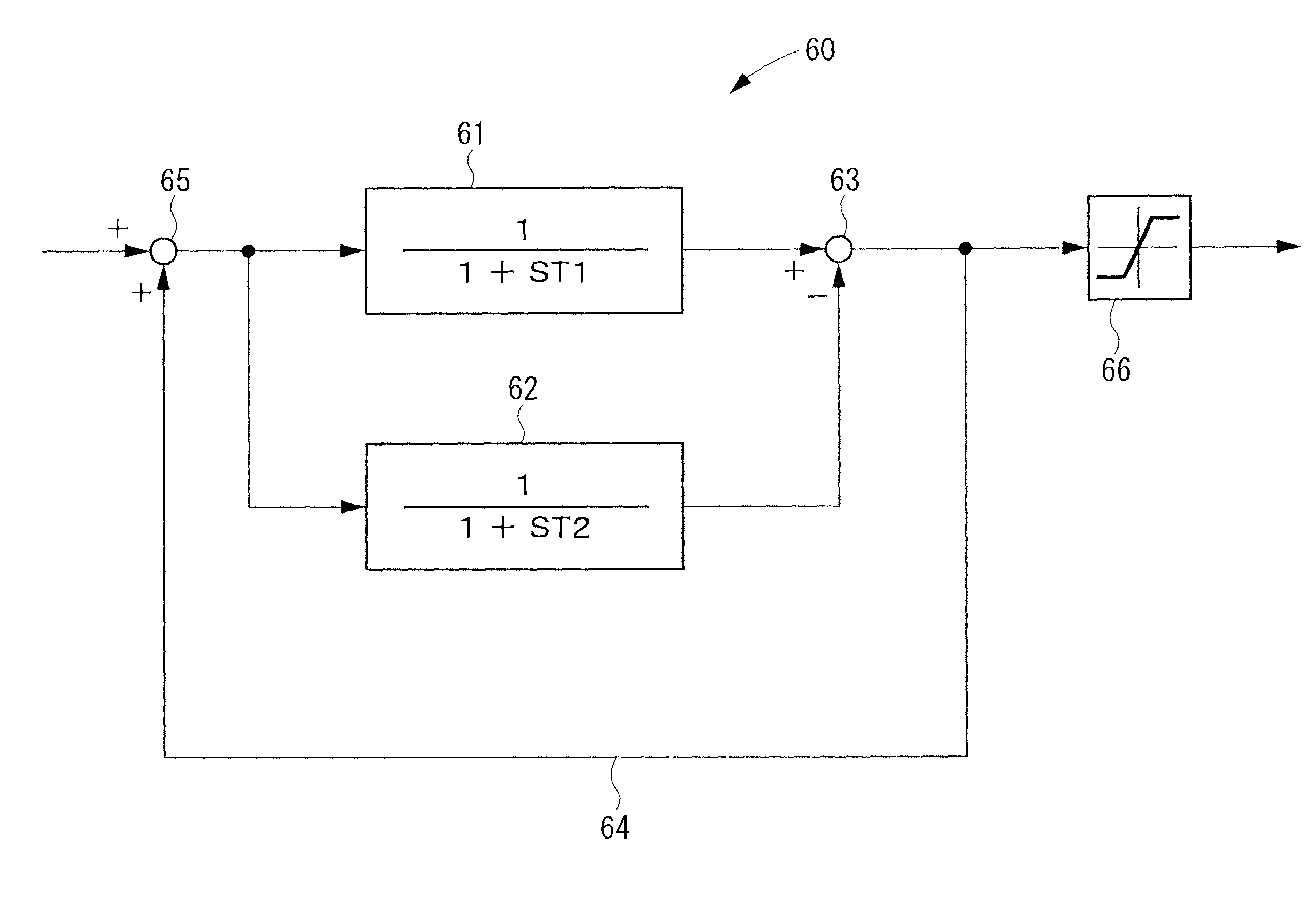
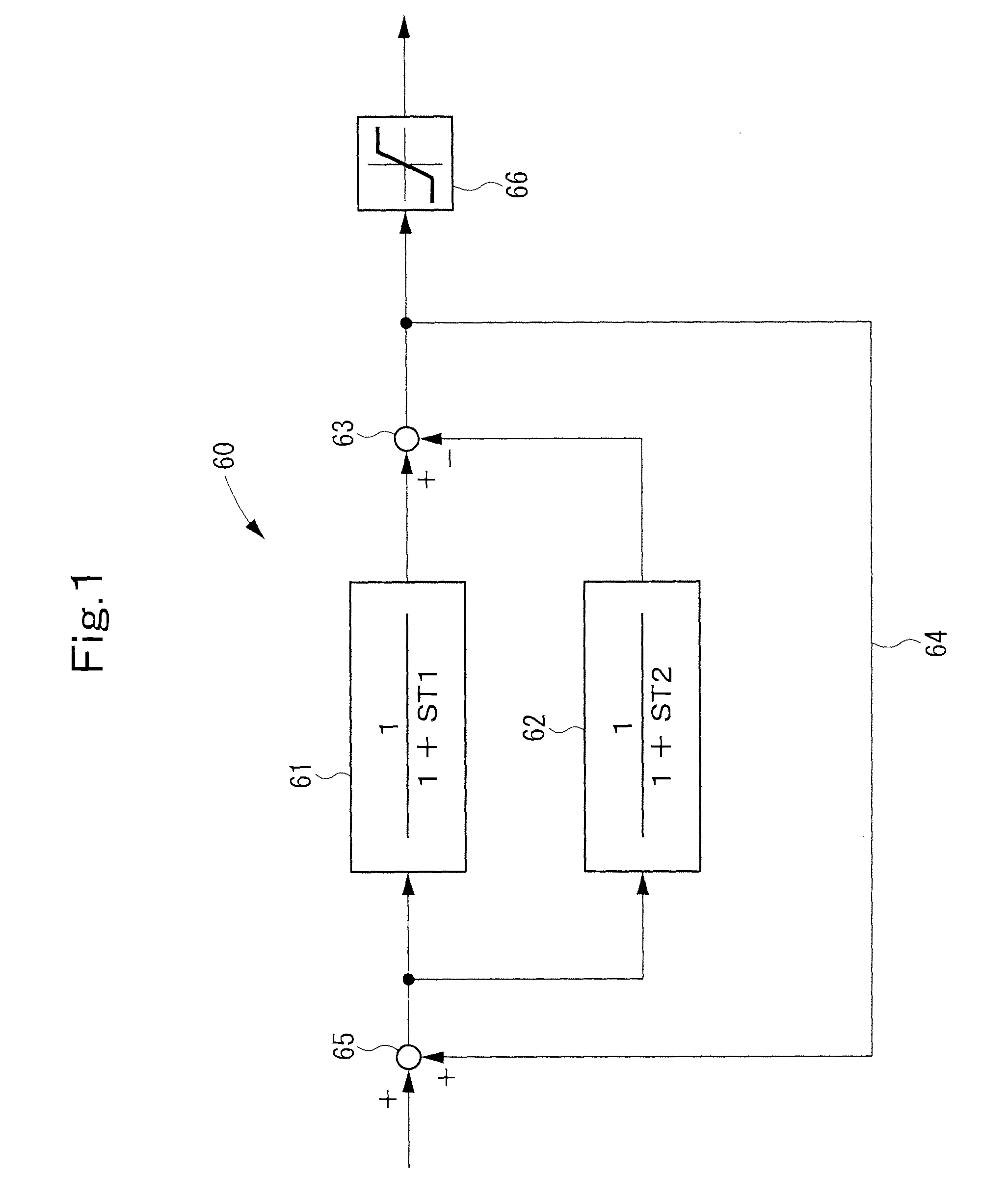
[0191]FIG. 1 shows a fluctuation detecting block 60 according to Embodiment 1 of the present invention. The fluctuation detecting block 60 is applied to the fluctuation detecting blocks 105, 106, 123, 124 (see FIG. 17) incorporated into the control unit 21 of the system stabilizing device 20 (see FIG. 16).

[0192]As shown in FIG. 1, the fluctuation detecting block 60 is composed of a low-pass filter 61, a low-pass filter 62, a subtracter 63, a feedback circuit 64, an adder 65, and a rating limiter 66.

[0193]The pass band frequency of the fluctuation detecting block 60 is determined by filtering characteristics required of the respective fluctuation detecting blocks 105, 106, 123, 124. The cut-off frequency on the high frequency side of the determined pass band frequency is set to be f1, the cut-off frequency on the low frequency side of the determined pass band frequency is set to be f2, the time constant of the low-pass filter 61 for noise removal with a cut-off frequency of f1 is set...

embodiment 2

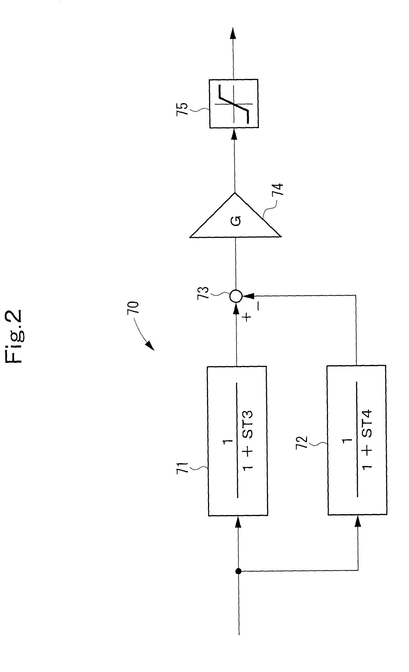
[0211]FIG. 2 shows a fluctuation detecting block 70 according to Embodiment 2 of the present invention. The fluctuation detecting block 70 is applied to the fluctuation detecting blocks 105, 106, 123, 124 (see FIG. 17) incorporated into the control unit 21 of the system stabilizing device 20 (see FIG. 16).

[0212]The fluctuation detecting block 70 of Embodiment 2 is an improvement on the fluctuation detecting block 60 of Embodiment 1, and represents a solution to the problem of Embodiment 1, namely, the problem that the characteristics are oscillatory.

[0213]As shown in FIG. 2, the fluctuation detecting block 70 is composed of a low-pass filter 71, a low-pass filter 72, a subtracter 73, an amplifier 74, and a rating limiter 75.

[0214]The pass band frequency of the fluctuation detecting block 70 is determined by filtering characteristics required of the respective fluctuation detecting blocks 105, 106, 123, 124. The cut-off frequency on the high frequency side of the determined pass band...

embodiment 3

[0236]In Embodiment 3, the configuration of the fluctuation detecting block 70 is itself the same as that in Embodiment 2, but the procedure of the method for designing the respective filters 71 and 72 of the fluctuation detecting block 70 is different.

[0237]In the designing method of Embodiment 3, the gain G is determined first, and then the setting number α is determined. By so doing, it becomes possible to carry out a design placing priority on the term of the gain G, rather than a design using the oscillation coefficient ζ as an indicator.

[0238]Concretely, upon comparison between the coefficients of the term of the gain shown by the Expression (1) and the term of the gain shown by the Expression (4), the setting number α after setting of the gain G is expressed by the following Formula (8).

[10thmathematicalformula]α=-(T2-T1)±(T2-T1)2+4G2·T1·T22T1·G(8)

[0239]The oscillation coefficient ζ is the same as that in the Formula (5) shown in Embodiment 2.

[0240]Here, the control unit 21 i...


PUM


Abstract

A control unit of a system stabilizing device uses a fluctuation detecting block (70A) to determine fluctuation components included in the active component and reactive component currents of a system current. The cut-off frequency on the high frequency side of the fluctuation detecting block (70A) is set to be f1; the cut-off frequency on the low frequency side is set to be f2; the time constant of a low-pass filter for noise removal which has a cut-off frequency of f1 is set to be T1; and the time constant of a low-pass filter for setting a fluctuation detection time which has a cut-off frequency of f2 is set to be T2. The fluctuation detecting block (70A) is composed of a low-pass filter (71) having first order lag characteristics with a time constant of T1, a low-pass filter (72) having first order lag characteristics with a time constant of T2, a subtracter (73) which performs subtraction between the output signals of the filter (71) and the filter (72) and outputs the difference, an amplifier (74) for amplifying the output of the subtracter (73), a rating limiter (75) for limiting the output of the amplifier, and an overcompensation inhibiting unit (200) which changes T4 to a smaller value when the rating limiter (75) performs a limiter action.

Description

TECHNICAL FIELD[0001]This invention relates to a system stabilizing device, which is designed to prevent an overcompensating action even if a load change or fluctuation exceeds the rating.BACKGROUND ART[0002]In recent years, power generation by natural energy such as sunlight or wind power has found use.[0003]FIG. 15 shows an example in which an existing power system (a system superior to a distribution system) 1 and a distribution system (micro grid) 10 are connected via a line impedance Ls and a circuit breaker 2.[0004]A dispersed generation plant 11 and a load 12 are connected to the distribution system 10 which is the micro grid. The dispersed generation plant 11 is illustrated as a single generator in FIG. 15. Actually, however, it is composed of a plurality of dispersed facilities for power generation, which include natural energy type power generation equipment utilizing natural energy (e.g., photovoltaic power generation equipment or wind power generation equipment), and int...

Claims


Application Information

Patent Timeline
IPC IPC(8): G06F1/28
CPCG05B5/01Y02E40/22H02J3/1842Y02E40/20
Inventor OI, KAZUNOBUMUNESHIMA, MASAKAZUMURAI, TAKAHIRO
Owner MEIDENSHA ELECTRIC MFG CO LTD
Why Eureka
Eureka Blog
Learn More