Hanging Stack and Rolling Rack

a technology of stacking rack and rolling rack, which is applied in the direction of dressing table, kitchen cabinets, cabinets, etc., can solve the problems of small items that cannot be rotated by the wide shelves, the unusual shape of the drawer is less suitable for large items, and the rotation motion of the wide shelves can be a problem for small items, etc., to achieve convenient maintenance, convenient storage, and convenient use.

Inactive Publication Date: 2021-07-15
ASHFIELD JAMES CURRIE
View PDF0 Cites 0 Cited by
  • Summary
  • Abstract
  • Description
  • Claims
  • Application Information

AI Technical Summary

Benefits of technology

[0029]5.5 It is easily maintained without disturbing the counter-top or the adjacent cabinets. The drawers can be removed from their slides. The rack and frame can be detached from the wheel-cars. The wheel-cars can be removed from the tracks.
[0030]The object of this invention was twofold. First, to provide an affordable solution to the corner-space access problem and second, to provide under-the-counter space to store a rolling step-stool, a safer, more convenient aide for reaching the wall cabinets than the usual little folding step-ladder, but one that needs more storage space.

Problems solved by technology

The rotating motion of wide shelves can be a problem for small items.
The size and unusually angled shapes of the drawers are less well-suited for large items.

Method used


Image

  • Hanging Stack and Rolling Rack
  • Hanging Stack and Rolling Rack
  • Hanging Stack and Rolling Rack

Examples


Embodiment Construction

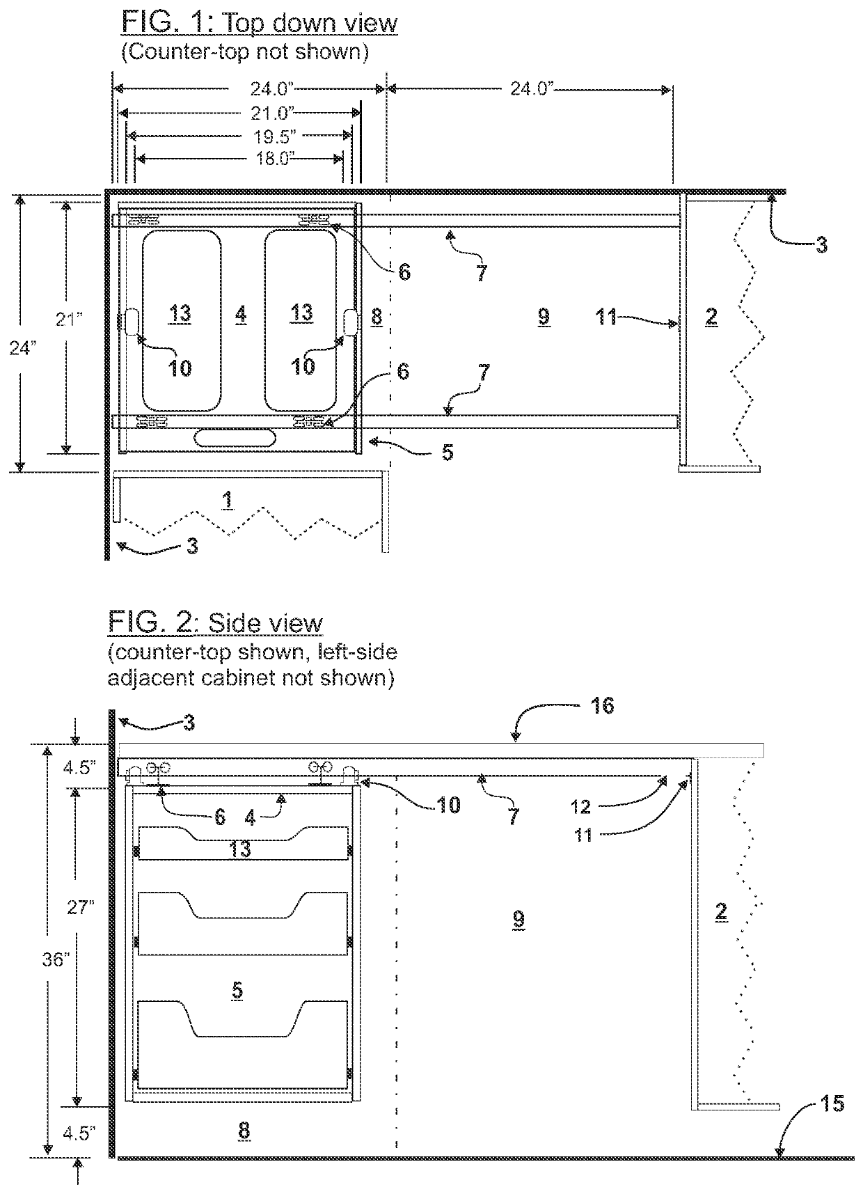
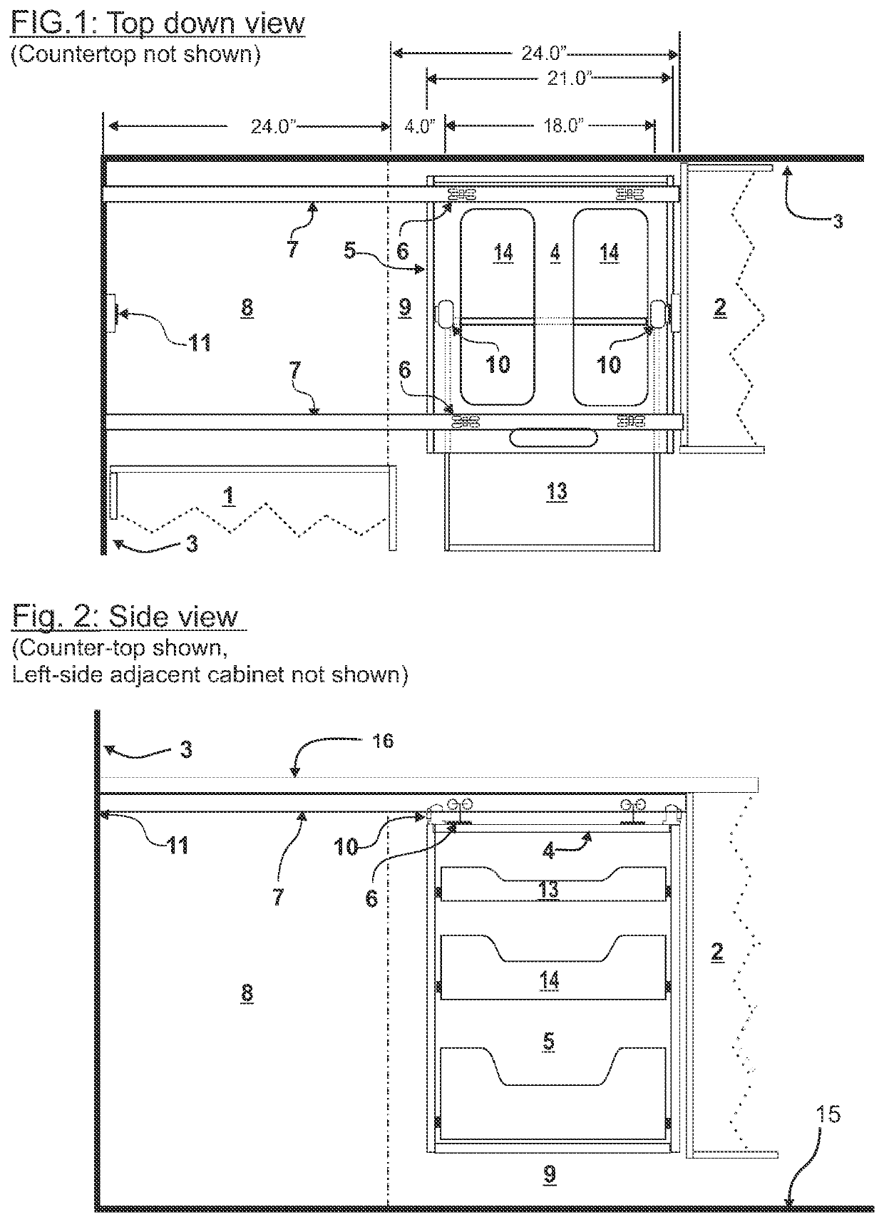
[0050]Drawing #1: Hanging Stack & Rolling Rack—Stack IN

[0051]FIG. 1: Top down view.

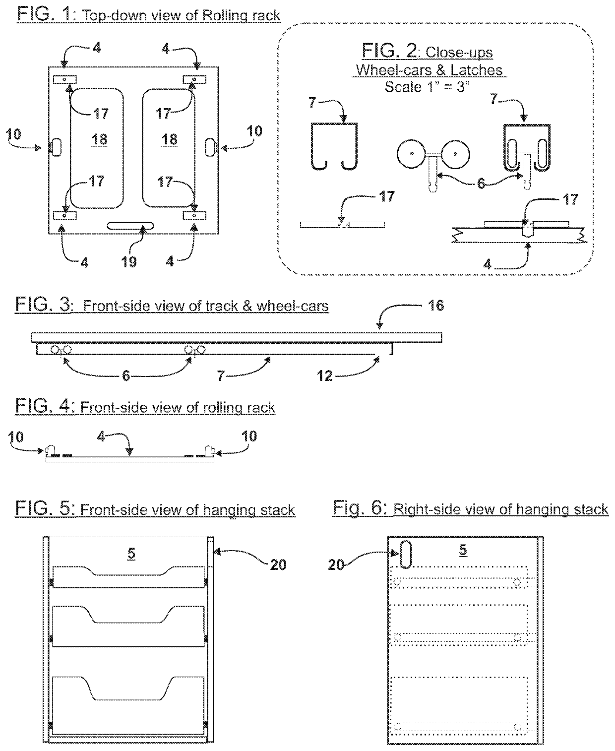
[0052]Counter-top is not shown. The numbers refer to the following:[0053]1. Left-side adjacent cabinet[0054]2. Right-side adjacent cabinet[0055]3. Kitchen wall[0056]4. Rolling rack[0057]5. Hanging Stack—frame and 3 drawers[0058]6. Wheel-cars, two per track[0059]7. Two tracks, 48″ long supported at ends[0060]8. Corner space occupied by hanging stack[0061]9. Shuffle space (empty)[0062]10. Bumper Magnet and spring[0063]11. Bumper stop and holder.[0064]13. Top drawer—visible thru openings in rack

[0065]FIG. 2: Side view

[0066]Counter-top shown, left-side adjacent cabinet & door not shown[0067]2. Right-side adjacent cabinet[0068]3. Kitchen wall[0069]4. Rolling rack[0070]5. Hanging stack—frame & 3 drawers[0071]6. Wheel-cars, two per track[0072]7. Two tracks, 48″ long supported at ends[0073]8. Corner space occupied by hanging stack[0074]9. Shuffle space (empty)[0075]10. Bumper Magnet and spring[0076]11. Bumper...


PUM


Abstract

A method for installing a set of drawers under the counter-top in the “blind corner” of kitchen cabinets. The stack of drawers is attached to a rack and hung from little wheel-cars in tracks. To access any of the drawers the door of the adjacent cabinet is opened and the stack is rolled sideways into borrowed space temporarily made available there. The drawers can then be pulled open. When finished the drawers are closed and the stack rolled back. Unlike existing products, this design's mechanisms permanently occupy very little of the adjacent space, only the top 3″. The rest is only borrowed. The flooring of this space is regular kitchen floor. It can be occupied by anything that can be easily moved out temporarily when corner access is needed.

Description

CROSS-REFERENCE TO RELATED APPLICATIONS[0001]Not ApplicableSTATEMENT REGARDING FEDERALLY SPONSORED RESEARCH OR DEVELOPMENT[0002]Not ApplicableTHE NAMES OF THE PARTIES TO A JOINT RESEARCH AGREEMENT[0003]Not ApplicableINCORPORATION-BY-REFERENCE OF MATERIAL SUBMITTED ON A COMPACT DISC OR AS TEXT FILE VIA THE OFFICE ELECTRONIC FILING SYSTEM[0004]Not applicableSTATEMENT REGARDING PRIOR DISCLOSURES BY THE INVENTOR OR A JOINT INVENTOR[0005]Not ApplicableBACKGROUND OF THE INVENTIONThe Blind Corner Problem[0006]In kitchens, the space under the counter-top in corners is difficult to access. If both adjacent cabinets were to have full sets of drawers the space would be completely inaccessible. This has led to the term “Blind Corner”. The least cost method to provide some access is to install shelves in one of the adjacent cabinets and extend them sideways throughout the blind corner. These shelves are so deep that getting to items in the back corner requires unpacking many of the items in fron...

Claims


Application Information

Patent Timeline
Patent Type & Authority Applications(United States)
IPC IPC(8): A47B77/02A47B88/40
CPCA47B77/02A47B2210/0062A47B2210/0043A47B88/40A47B77/04A47B46/00A47B67/04A47B81/002
Inventor ASHFIELD, JAMES CURRIE
Owner ASHFIELD JAMES CURRIE
Why Eureka
Try Eureka