
Fluid Control Device

a technology of fluid control device and fluid leakage, which is applied in the direction of diaphragm valves, valve housings, instruments, etc., can solve the problems of fluid leakage or the like more easily, and achieve the effect of accurately detecting a leakag

Active Publication Date: 2021-07-15
FUJIKIN INC
View PDF0 Cites 1 Cited by
  • Summary
  • Abstract
  • Description
  • Claims
  • Application Information

AI Technical Summary

Benefits of technology

The present invention helps to detect leaks of fluids accurately, even if the leakage is small.

Problems solved by technology

However, such a film forming process requires a fluid controller, which supplies fluid to a film forming apparatus, to perform switching operations at a very high frequency, and such load can cause fluid to leak or the like more easily.
Further, because highly reactive and extremely toxic gas is used in semiconductor manufacturing processes, it is important to be able to remotely detect leaks while the leaks are small.

Method used


Image

  • Fluid Control Device
  • Fluid Control Device
  • Fluid Control Device

Examples


example 1

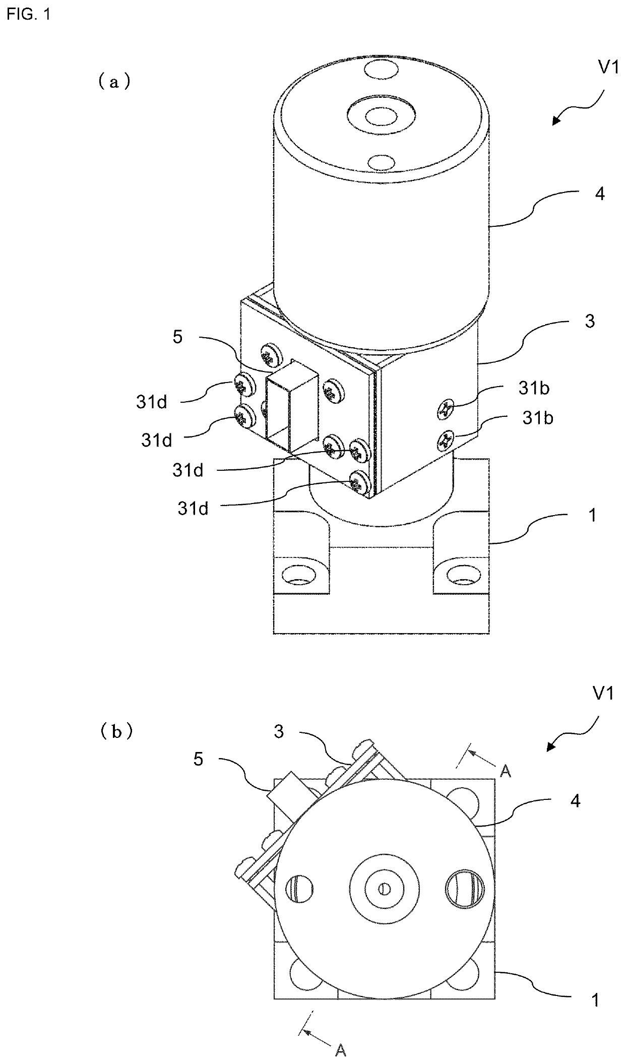
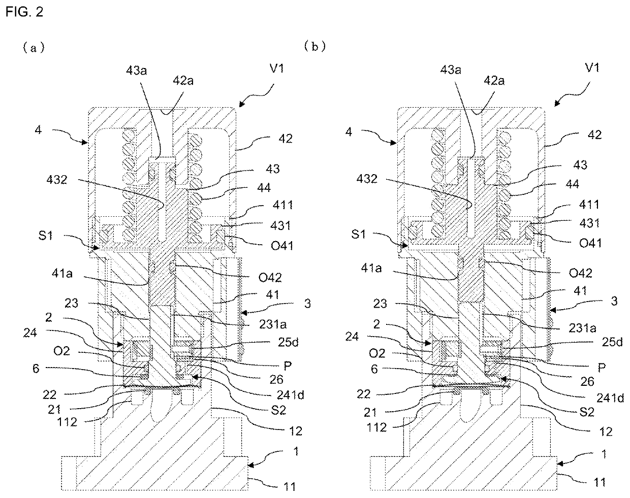
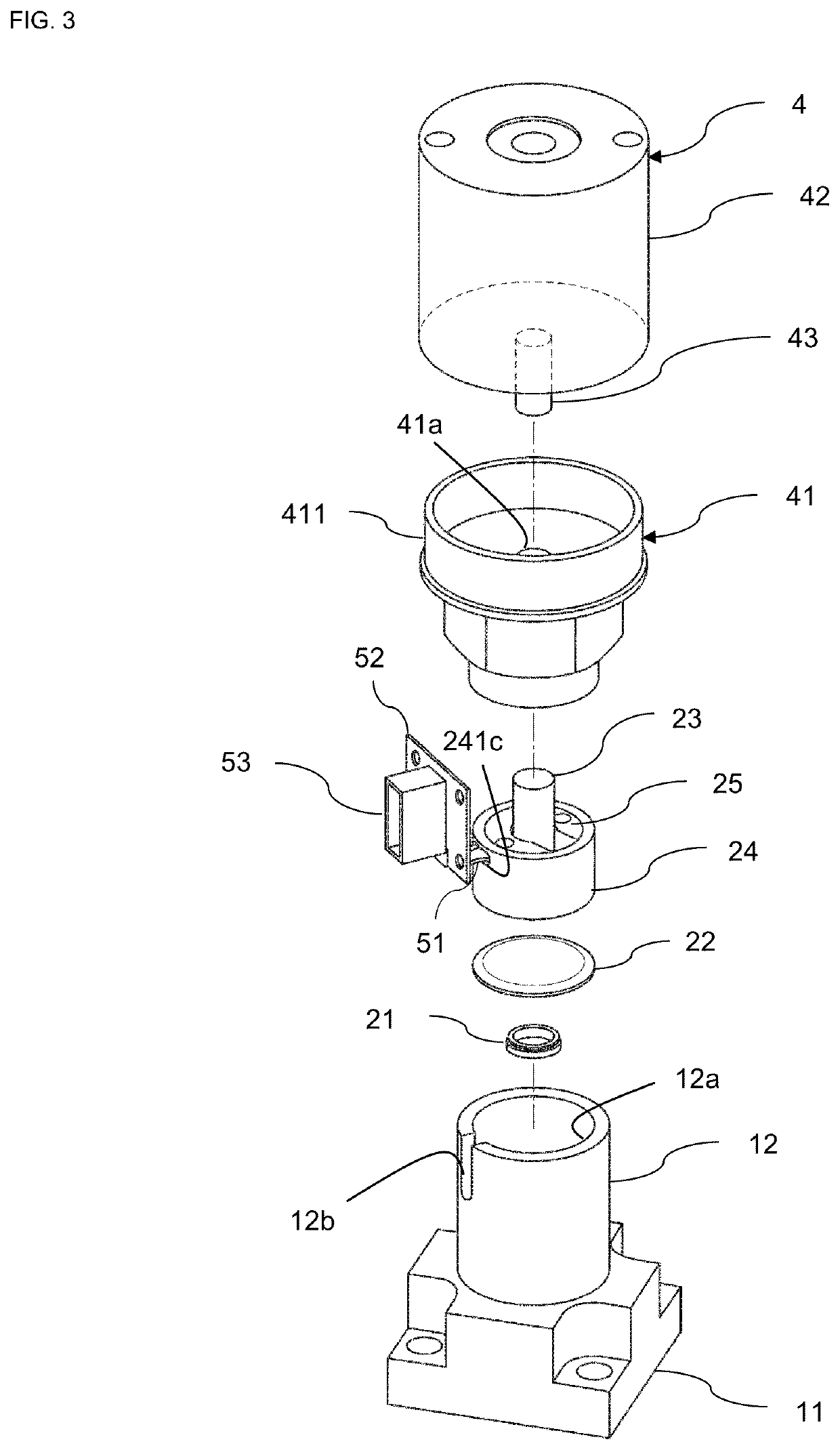
[0030]A fluid control device according to an embodiment of the present invention will be described below with reference to the drawings.

[0031]In the following description, the directions of members and the like may be referred to as upper, lower, left, and right depending on the directions in the drawings for the sake of convenience, but these do not limit the directions of members or the like in the actual situation or an embodiment of the present invention.

[0032]As illustrated in FIG. 1, a fluid control device V1 according to the present embodiment is a device capable of detecting an internal operation by an internal sensor and can detect abnormality of the fluid control device V1 based on a detected information, particularly a leakage of fluid within the fluid control device V1. Further, this fluid control device V1 is connected to an external terminal and provides information related to the abnormality of the fluid control device V1 and detected by the sensor to the external ter...

example 2

[0131]Next, a fluid control device according to a second embodiment of the present invention will be described.

[0132]As illustrated in FIG. 7 and FIG. 8, a fluid control device V2 according to the present embodiment includes a storing part 24b storing an elastic body 9 in the bonnet 24.

[0133]In the description of the fluid control device V2 according to the present embodiment, the fluid control device V2 is referred to as a modification of the fluid control device V1 according to the first embodiment described above, members having the same function and configuration are designated by the same reference numerals as those of the fluid control device V1, and the description thereof will be omitted.

[0134]The bonnet 24 in the present embodiment is provided with a substantially concave storing part 24b opening toward the closed space S2 side and storing the elastic body 9 from an opening. In particular, in the present embodiment, the storing part 24b forms a part of the penetration hole ...


PUM


Abstract

A fluid control device, capable of detecting leaks even if the leaks is slight, is provided. The fluid control device includes a valve body in which the flow path is formed, a diaphragm isolating a closed space from the flow path, a bonnet forming the closed space between the diaphragm and providing a penetration hole connected to the closed space and penetrated to be able to vertically move a diaphragm retainer, the diaphragm retainer vertically moving in the penetration hole to press the diaphragm and providing an increased diameter portion not to be removed from the penetration hole, a pressure sensor detecting a pressure inside of the closed space, and an elastic body interposing between the increased diameter portion of the diaphragm retainer and the bonnet inside of the closed space and elastically expanding and deflating between the increased diameter portion of the diaphragm retainer and the bonnet as the diaphragm retainer vertically moves.

Description

TECHNICAL FIELD[0001]The present invention relates to a technique for detecting fluid leakage in a fluid control device.BACKGROUND ART[0002]Conventionally, a film forming process to form thin films on surfaces of semiconductor wafers required a precise control of film thickness, and in recent years a film forming method called ALD (Atomic Layer Deposition) has been used for forming a thin film with an atomic or molecular level thickness.[0003]However, such a film forming process requires a fluid controller, which supplies fluid to a film forming apparatus, to perform switching operations at a very high frequency, and such load can cause fluid to leak or the like more easily. Therefore, there is a high demand for technology that can easily detect fluid leakage in a fluid controller.[0004]Further, because highly reactive and extremely toxic gas is used in semiconductor manufacturing processes, it is important to be able to remotely detect leaks while the leaks are small.[0005]On this ...

Claims


Application Information

Patent Timeline
Patent Type & Authority Applications(United States)
IPC IPC(8): F16K37/00F16K7/16G01M3/28
CPCF16K37/0066G01M3/2876F16K7/16F16K31/1221F16K37/0041F16K7/12F16K37/00F16K37/005G01M3/26F16K31/1266F16K31/1225F16K7/17F16K27/0236
Inventor TANNO, RYUTAROSHINOHARA, TSUTOMUSUZUKI, YUYAKISO, HIDENORIWATANABE, YOSHIAKI
Owner FUJIKIN INC
Learn More