Smart lighting foot mat

Inactive Publication Date: 2021-07-15
DEXIN ELECTRONICS LTD +1
View PDF0 Cites 0 Cited by
  • Summary
  • Abstract
  • Description
  • Claims
  • Application Information

AI Technical Summary

Benefits of technology

[0008]Therefore, a smart lighting foot mat of the present disclosure is able to provide illumination and generate different lighting st

Problems solved by technology

However, despite the advancement to vehicle foot mats, appl

Method used


Image

  • Smart lighting foot mat
  • Smart lighting foot mat
  • Smart lighting foot mat

Examples


first embodiment

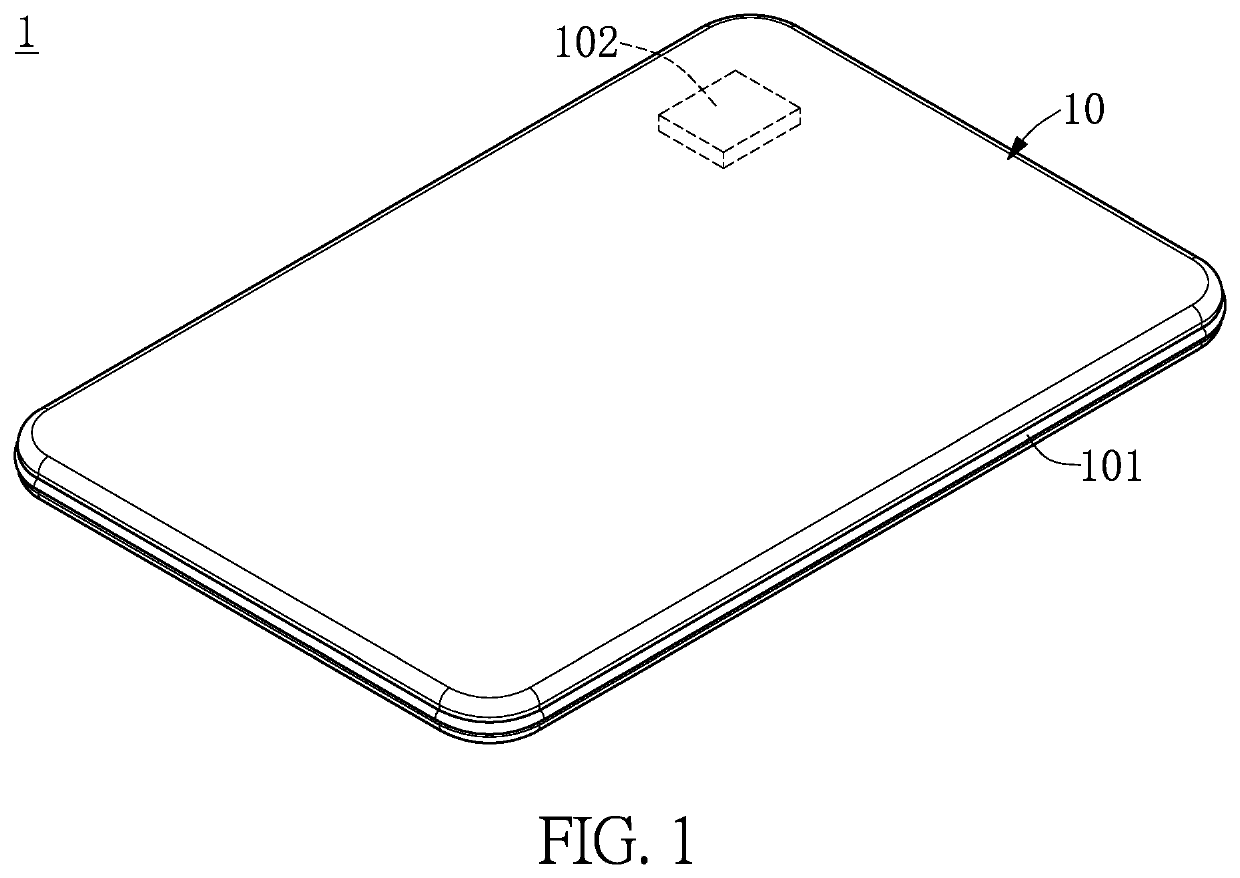
[0020]Referring to FIG. 1, a schematic view of a smart lighting foot mat 1 of one embodiment of the present disclosure is provided. The smart lighting foot mat 1 includes a foot mat body 10. As shown in FIG. 1, the foot mat body 10 is exemplified as being rectangular in this embodiment. The foot mat body 10 can also be rectangular, round, or other shapes, and the shape of the foot mat body 10 is not limited in the present disclosure. The foot mat body 10 includes a lighting device 101 and a control unit 102.

[0021]The lighting device 101 is disposed at the edge of the foot mat body 10. The lighting device 101 can be an LED light bar or other flexible light bars, but the types of the lighting device 101 are not limited thereto. The lighting device 101 can be disposed at the edge of the foot mat body 10 by adhesion or embedding, but the manners by which the lighting device 101 can be configured at the edge of the foot mat body 10 are not limited thereto.

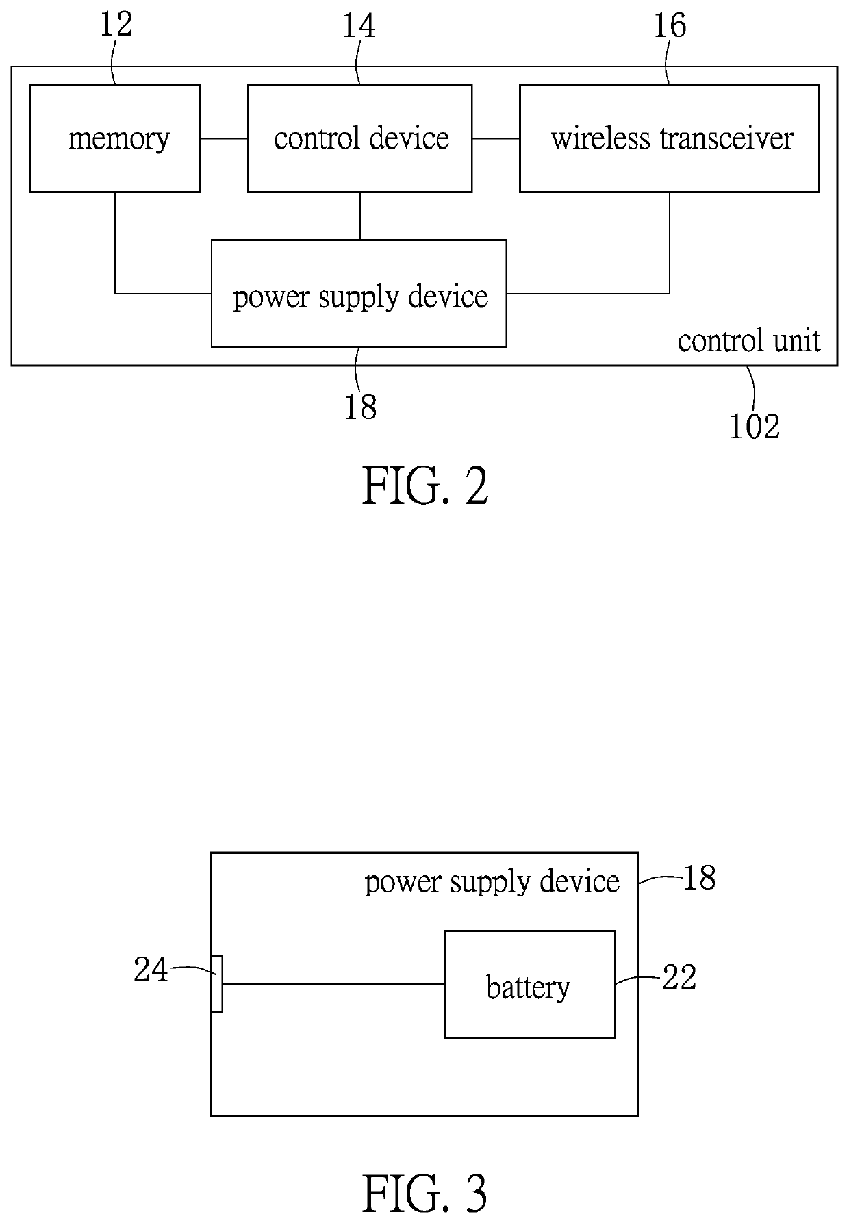
[0022]The control unit 102 is di...

second embodiment

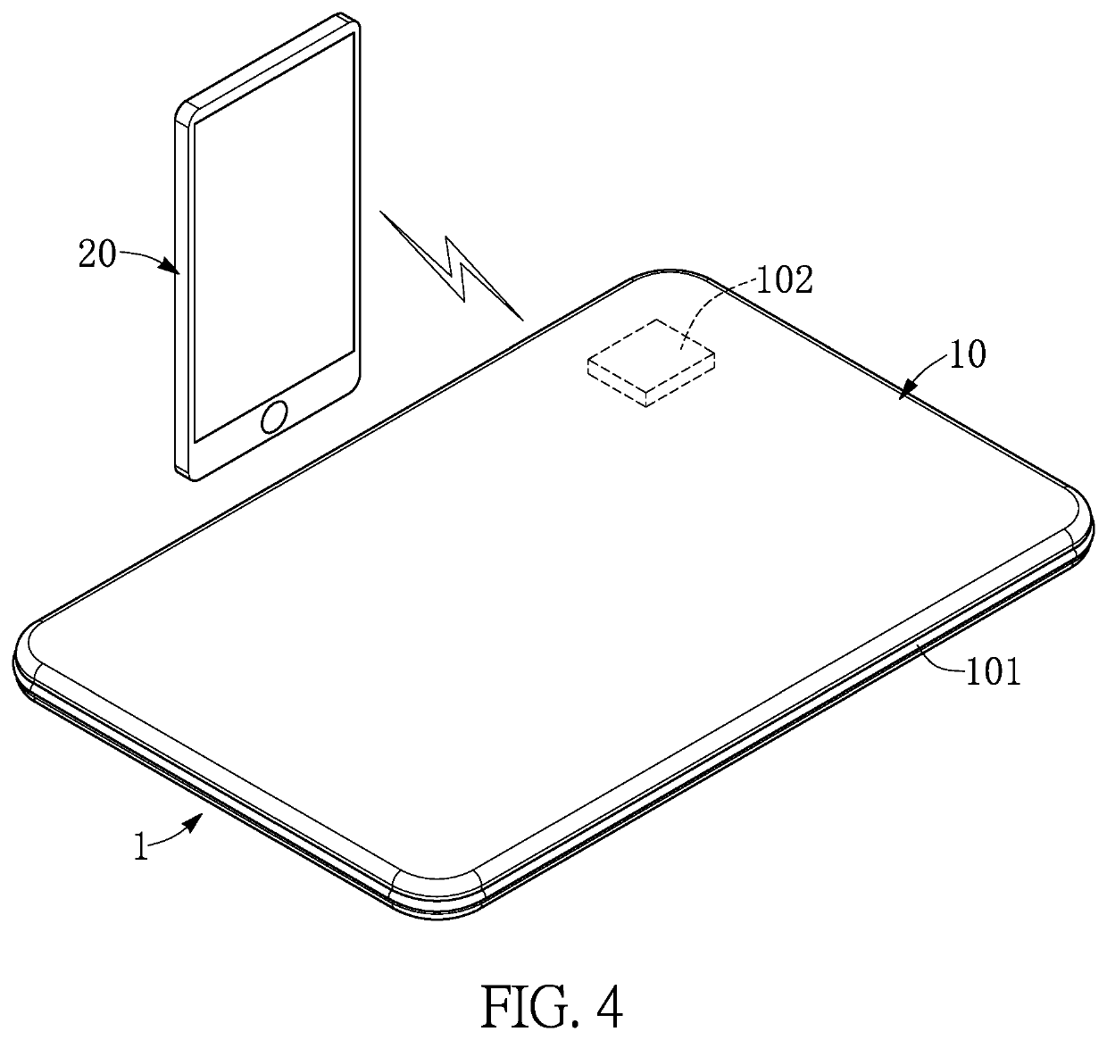
[0034]Reference is made to FIG. 5, and in conjunction with FIG. 1 and FIG. 2. FIG. 5 is a schematic view of the smart lighting foot mat 2 of another embodiment of the present disclosure. The smart lighting foot mat 2 includes a foot mat body 4. A control circuit 26 of the smart lighting foot mat 2 further includes a keyboard interface 28, and a first button 281 and a second button 282 disposed on the keyboard interface 28. The keyboard interface 28 is electrically connected to the control device 14, and the control device 14 receives a keyboard signal when the keyboard interface 28 is pressed. The control device 14 wirelessly controls an operation of the mobile communication device 20 according to the keyboard signal by the wireless transceiver 16. When the control device 14 receives the caller ID of the mobile communication device 20, the control device 14 activates the first button 281 and the second button 282 on the keyboard interface 28 to proceed with an incoming call operatio...

third embodiment

[0049]Referring to FIG. 7, a system block diagram of a control circuit 30 of another embodiment of the present disclosure is provided. The control circuit 30 further includes a sound receiver 301 and a sound recognizer 302. The sound receiver 301 and the sound recognizer 302 are electrically connected to the control device 14 in the control unit 102. The sound recognizer 302 recognizes a sound signal received by the sound receiver 301. The control device 14 controls the flickering frequency, the color brightness, or the color changing frequency of the lighting state of the lighting device 101.

[0050]For example, users may encounter situations where they are unable to control the lighting state of the lighting device 101, since they may have to focus on driving. Users may encounter situations where it is inconvenient to press the keyboard interface 28 to control the lighting state of the lighting device 101 by foot, as when encountering poor terrain and having to step on the accelerat...


PUM


Abstract

A smart lighting foot mat includes a foot mat body including a lighting device and a control unit. The control unit includes a memory storing a lighting state list of the lighting device. The lighting state list stores a plurality of lighting states and a plurality of codes corresponding to the plurality of lighting states, a control device controlling a lighting state of the lighting device according to the plurality of codes and a wireless transceiver receiving a wireless control signal and transmitting the wireless control signal to the control device. The control device analyzes the wireless control signal to obtain a code, compares the code with the plurality of codes in the lighting state list and controls the lighting device according to the code to generate a lighting state corresponding to the code.

Description

CROSS-REFERENCE TO RELATED PATENT APPLICATION[0001]This application claims the benefit of priority to Taiwan Patent Application No. 109101292, filed on Jan. 15, 2020. The entire content of the above identified application is incorporated herein by reference.[0002]Some references, which may include patents, patent applications and various publications, may be cited and discussed in the description of this disclosure. The citation and / or discussion of such references is provided merely to clarify the description of the present disclosure and is not an admission that any such reference is “prior art” to the disclosure described herein. All references cited and discussed in this specification are incorporated herein by reference in their entireties and to the same extent as if each reference was individually incorporated by reference.FIELD OF THE DISCLOSURE The present disclosure relates to a foot mat, and more particularly to a smart lighting foot mat.BACKGROUND OF THE DISCLOSURE[0003]...

Claims


Application Information

Patent Timeline
IPC IPC(8): H05B47/19G08C17/02H05B47/12
CPCH05B47/19H04M1/72533H05B47/12G08C17/02H04M1/72415H05B45/10H05B45/20H04M1/72412G08C2201/93Y02B20/40
Inventor LU, HO-LUNGCHEN, SHU-SHENGLIN, CHIN-LUNG
Owner DEXIN ELECTRONICS LTD
Why Eureka
Try Eureka