Device for accommodating a cable assembly

a technology for a device and a cable, which is applied in the direction of electric/fluid circuit, electric apparatus, transportation and packaging, etc. it can solve the problems of increasing the risk of fracture in devices known from the prior, the particular susceptible to fracture of the receiving portion, and the conventional devices for accommodating cable assemblies under such conditions cannot guarantee reliable fastening, so as to achieve more reliable fastening of the casing and cover

Pending Publication Date: 2021-07-29
A RAYMOND & CO
View PDF23 Cites 0 Cited by
  • Summary
  • Abstract
  • Description
  • Claims
  • Application Information

AI Technical Summary

Benefits of technology

[0004]The object of the present invention is therefore to propose a device for accommodating elongate elements or a grouping of elongate elements which ensures more reliable fastening of casing and cover.

Problems solved by technology

At this location, a weld line results in the later finished receiving portion, which results in the receiving portion being particularly susceptible to fracture at this location.
This is particularly disadvantageous since receiving portions are sometimes exposed to high operating forces.
Conventional devices for accommodating cable assemblies under such conditions cannot guarantee reliable fastening.
In addition to high operating forces, low temperatures in particular also increase the risk of fracture in devices known from the prior art.

Method used


Image

  • Device for accommodating a cable assembly
  • Device for accommodating a cable assembly

Examples


Embodiment Construction

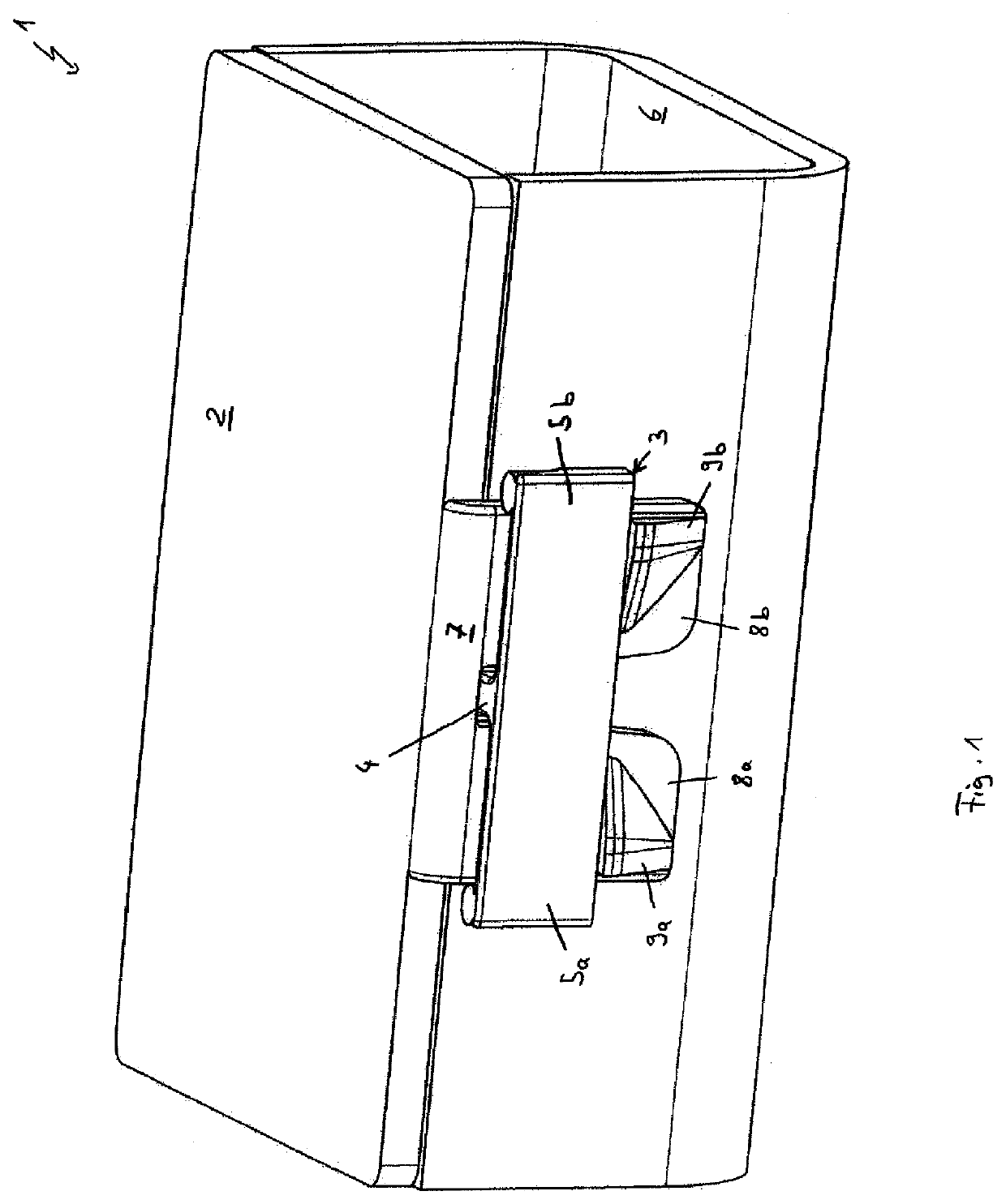
[0033]FIG. 1 shows a perspective view of an exemplary embodiment of the device 1 according to the invention for accommodating a cable assembly in the closed state. The device 1 comprises a casing, which in the present case is a housing. The housing 2, which has a receiving portion 3 with a connecting piece 4. Receiving portion and housing are formed in one piece and in this example are made of plastic, wherein they have been produced by injection molding. The connecting piece 4 is connected at its first end to the housing 2 and extends away from the housing toward the second end. Furthermore, the receiving portion 3 has two side sections 5a, 5b which are each connected at one end to the connecting piece 4, extend away from the connecting piece 4 toward the other end, and extend in different directions. The side sections 5a, 5b of this exemplary embodiment are connected to the second end of the connecting piece 4 and extend in diametrically different directions.

[0034]The device 1 fur...


PUM


Abstract

Disclosed is a device for accommodating a cable assembly. The device comprises a casing having a receiving portion with a connecting piece which is connected at its first end to the casing and extends away from the casing toward its second end; with two side sections each connected to the connecting piece at one end, extending toward the other end away from the connecting piece, and extending in different directions. The device further comprises a cover having an insertion part for insertion into the receiving portion, the insertion part having two sub-sections and each sub-section has an engaging element. The device is designed such that the insertion part can be inserted into the receiving portion, wherein the connecting piece is then located between the sub-sections. When the insertion part is inserted until each engaging element has passed a side section, the engaging elements prevent the insertion part from sliding out.

Description

CROSS-REFERENCE TO RELATED APPLICATIONS[0001]This application is the U.S. National Stage Application of International Patent Appl. No. PCT / EP2019 / 061536 filed on 6 May 2019, which claims priority to and all advantages of German Patent Appl. No. 10 2018 003 688.0 filed on 7 May 2018, the contents of which are hereby incorporated by reference.FIELD OF THE INVENTION[0002]The invention relates to a device for accommodating a cable assembly. The invention also relates to a system comprising device and cable assembly.BACKGROUND OF THE INVENTION[0003]Devices for accommodating a cable assembly are known from the prior art. They usually have a casing, in which the cable assembly is accommodated, and a cover. The casing is generally a housing. The cover is locked to the housing by means of a fastener. The fastener in this case consists of a receiving portion and an insertion part which is intended to be inserted into the receiving portion in order to close the fastener. The receiving portion ...

Claims


Application Information

Patent Timeline
Patent Type & Authority Applications(United States)
IPC IPC(8): H02G3/04
CPCH02G3/0418B60R16/0215H02G3/0456H02G3/0487H02G3/0437
Inventor TAUSENDFREUND, THOMASGLAGAU, ANDREASJUNGE, ANDYKRÜGER, FRANZISKAKOLB, CHRISTIAN
Owner A RAYMOND & CO
Why Eureka
Try Eureka