

Non-Slip Tool For Manipulating A Cord
- Summary
- Abstract
- Description
- Claims
- Application Information
AI Technical Summary
Benefits of technology
Problems solved by technology
Method used
Image

Examples
all embodiments
[0039]In an embodiment:
[0040]The Plane of the Holder is a plane parallel to the largest faces of the smallest rectangular cuboid which completely contains the Handler and which contains the Axis of the Handle.
[0041]The Handler comprises a Handle and a Holder.
[0042]The Contact Surface is the surface of the Holder that is uppermost when the Actor holds the Handler upright, meaning with the Handle held vertically and the Holder above it.
[0043]The Contact Surface contains at least one Gripper and at least one Slider.
[0044]A Gripper is a surface of the Holder that is adapted to prevent a Cord from sliding against it by means of friction between the Gripper and the Cord.
[0045]A Slider is a surface of the Holder that is adapted to allow a Cord to slide against it perpendicular to the Plane of the Holder.
[0046]In some embodiments Slider presents a downward concavity. This restricts a Cord engaged with a Slider from slipping against the Slider in a direction other than one perpendicular to t...
example embodiment 1
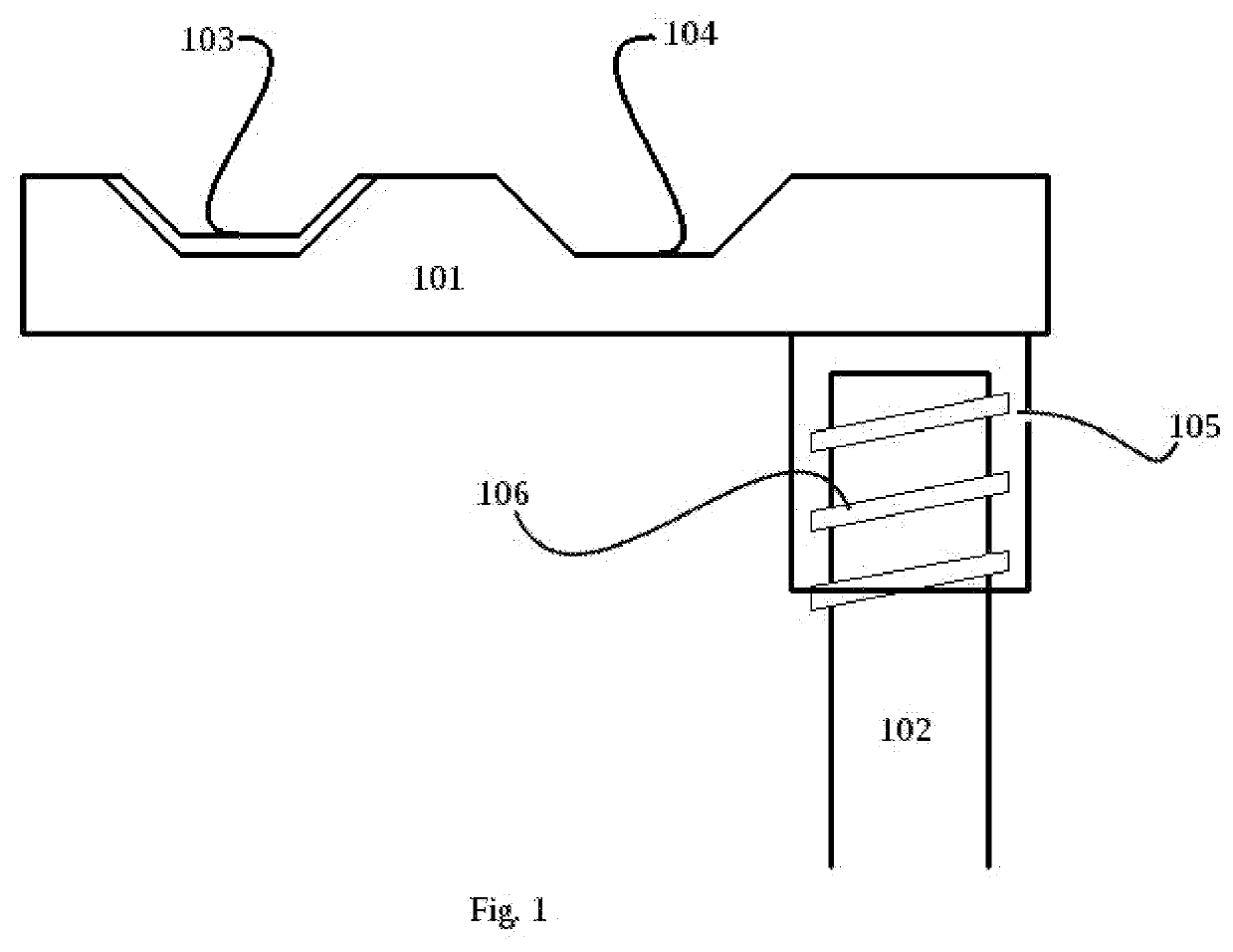
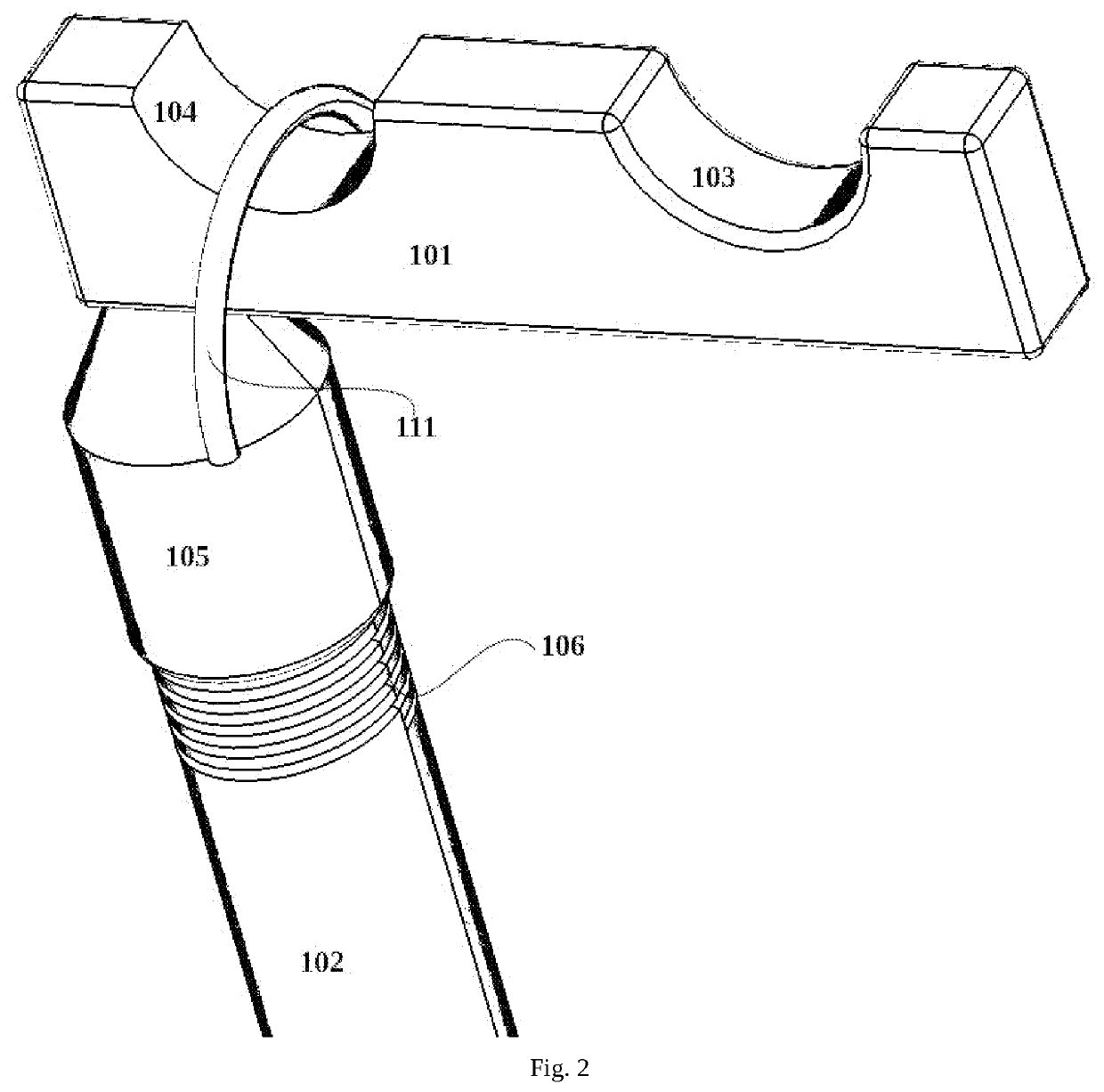
[0071]In an embodiment as shown in FIG. 1 and FIG. 2 a Handler is specially adapted to put up and bring down a string of Christmas lights. Such a string of lights comprises sections of Cord and lights between them. The sections of Cord contain electrically conducting wire completely enclosed in a non-conducting rubber or elastomer casing.
[0072]The Handler Tool comprises a telescoping handle (102), and a Holder (101) made of plastic. In this embodiment the Handle screws into an Insertion Point (105) of the Holder.
[0073]The body of the Holder is shaped to be longest in a direction perpendicular to the rod, and flat at its top which is defined to be the side away from the length of rod.
[0074]The natural means of holding the Holder is for the Actor to hold the Handler vertically or almost vertically. In this case the Actor can raise the Holder against a Cord so that the Cord rests on the Gripper (103) or the Slider (104), by the choice of the Actor. If the Actor raises the Cord against ...
example embodiment 2
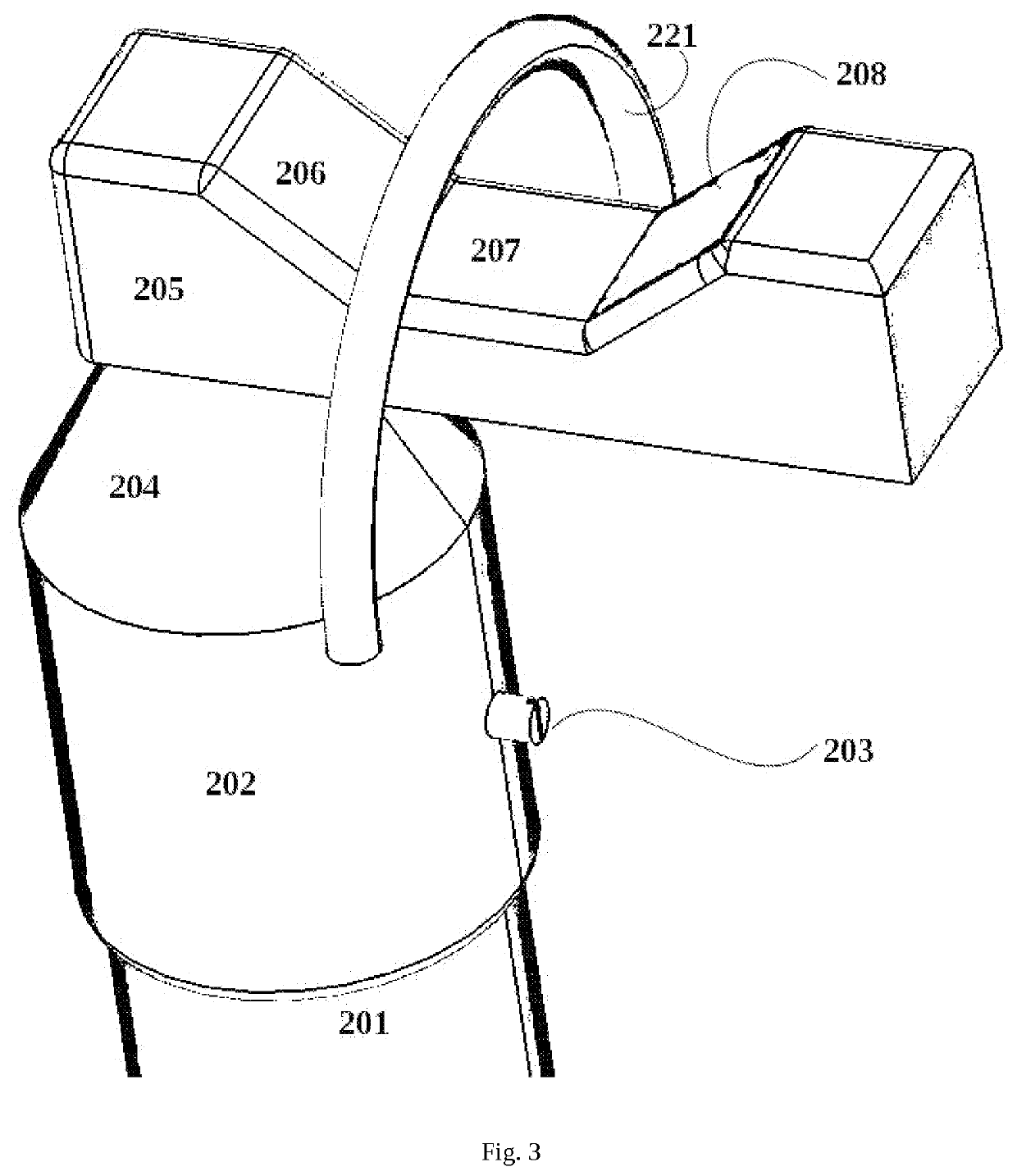
[0075]In an embodiment as shown in FIG. 3 a Handler is specially adapted to put up and bring down a string of Christmas lights. Such a string of lights comprises sections of Cord and lights between them. The sections of Cord contain electrically conducting wire completely enclosed in a non-conducting rubber or elastomer casing.
[0076]The Handler Tool comprises a Handle (201), and a Holder (205) made of plastic. In this embodiment the Handle (201) inserts into the Insertion Point (202) straight and is kept in place by a Screw (203).
[0077]The body of the Holder is shaped to be longest in a direction perpendicular to the rod, and flat at its top which is defined to be the side away from the length of rod.
[0078]In this embodiment the Holder has a Gripper (206, 207, 208) which is a surface covered by an elastomer adapted to grip at a Cord (221) pressing against it. In this embodiment there is no Slider.
[0079]The natural means of holding the Holder is for the Actor to hold the Handler vert...
PUM
 Abstract
Description
Claims
Application Information