An orthodontic system for the orthodontic treatment of a patient's teeth, a method for the placement of an appliance for the orthodontic treatment of a patient's teeth, and a use of the appliance of such an orthodontic system

Pending Publication Date: 2021-08-12
3 C SARL
View PDF2 Cites 5 Cited by
  • Summary
  • Abstract
  • Description
  • Claims
  • Application Information

AI Technical Summary

Benefits of technology

[0043]Another aim of the present disclosure is that of providing a method for the placement of an appliance for the orthodontic treatment of a patient's teeth not having at least some of the drawbacks of the orthodon

Problems solved by technology

The problem of these orthodontic appliances lies, inter alia, in the placement thereof and in the time required for this placement.
It is therefore easy to understand that a standard bracket, i.e. mass-produced, will never allow the expression of the optimal movement of the tooth.
The placement of such orthodontic appliances even if performed by specialists in the field (orthodontists) remains hazardous in some cases.
The precise positioning of the brackets on the teeth remains difficult and makes it hardly possible to obtain an ideal alignment due to the variable morphology of the labial and/or lingual surfaces of the teeth.
In these two scenarios, the following problems arise:In order to reposition the brackets correctly on the malocclusion model, it is for example necessary to manufacture a plaster malocclusion model or imprint the malocclusion model directly by stereolithography.It is then necessary to produce a mould on top, referred to as a transfer tray which is frequently made of silicone or is thermoformed: this is not always very precise as it is necessary to release the whole (transfer tray and brackets produced) and subsequently replace the brackets very precisely in this tray.
Any inaccurate placement of the brackets in the tray reduces the benefit of customized systems.Second source of imprecision: as the tra

Method used


Image

  • An orthodontic system for the orthodontic treatment of a patient's teeth, a method for the placement of an appliance for the orthodontic treatment of a patient's teeth, and a use of the appliance of such an orthodontic system
  • An orthodontic system for the orthodontic treatment of a patient's teeth, a method for the placement of an appliance for the orthodontic treatment of a patient's teeth, and a use of the appliance of such an orthodontic system
  • An orthodontic system for the orthodontic treatment of a patient's teeth, a method for the placement of an appliance for the orthodontic treatment of a patient's teeth, and a use of the appliance of such an orthodontic system

Examples


Embodiment Construction

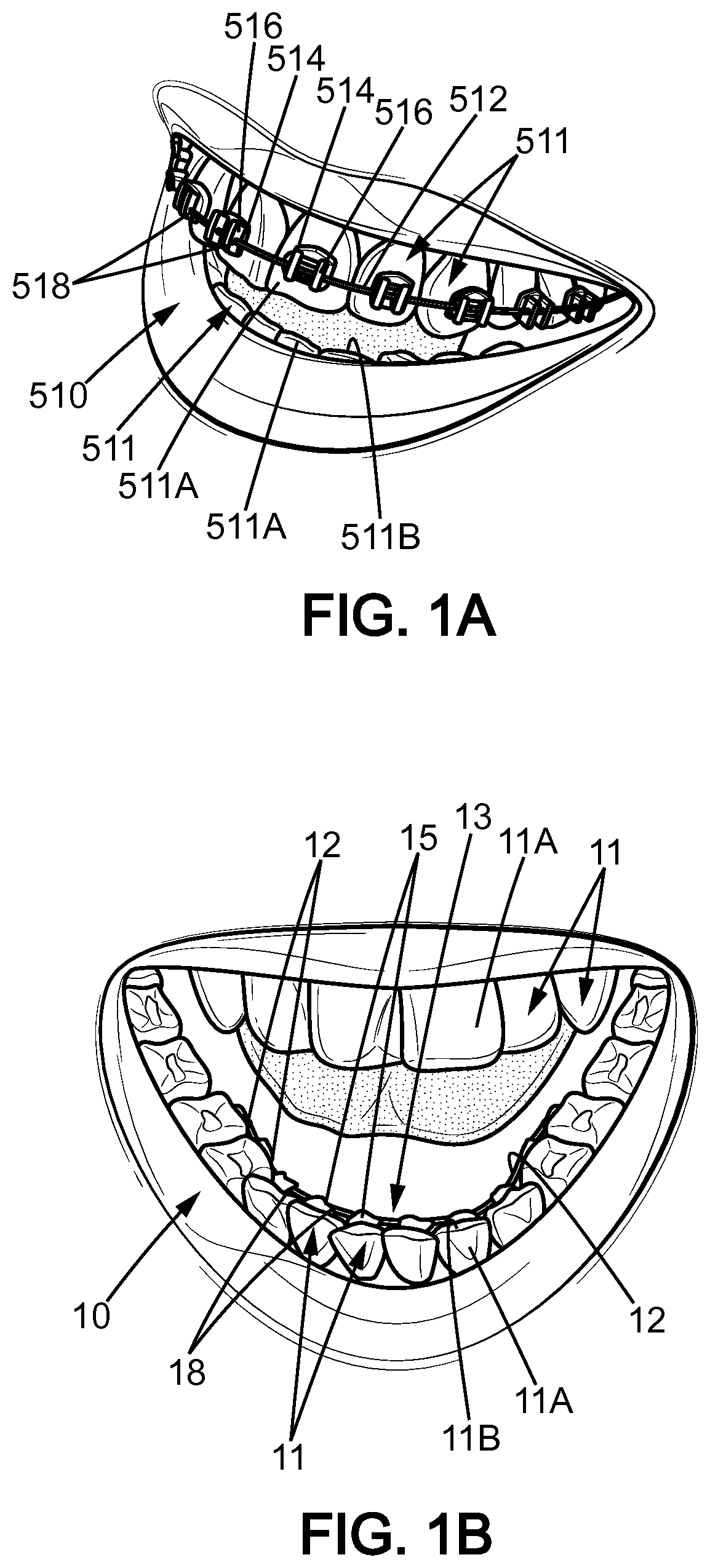
[0073]FIG. 1A illustrates schematically an orthodontic appliance 510 known in the prior art and placed on a patient's teeth 511 according to a method known from the prior art. The appliance 510 comprises an orthodontic wire 512 and a plurality of brackets 516 and bases 514. Each base 514 is fixed between a corresponding tooth 511 and bracket 516. Each bracket 516 is provided with a slot 518 wherein the orthodontic wire 512 is inserted.

[0074]Generally, as disclosed in document U.S. Pat. No. 8,678,817 B2, such a bracket includes a mounting base for attachment to a tooth surface and an archwire slot formed upon the base and sized for receiving an orthodontic archwire (or orthodontic wire).

[0075]FIG. 1A schematically illustrates an appliance 510 known in the prior art that consists of a labial version, wherein the brackets are arranged on the outer (labial) surface 511A of the teeth 511. The orthodontic wire 512 is inserted into the slots 518 of the brackets 516 so as to align the teeth...


PUM


Abstract

Method for the placement of an appliance, orthodontic system for the orthodontic treatment of a patient's teeth and use of the appliance of the orthodontic system, the orthodontic system including an appliance and a jig, wherein the appliance includes pearls which are each provided with a slot into which an orthodontic wire can be inserted, wherein the pearls are interconnected by the jig and wherein the jig includes separated caps, the caps being shaped individually to the shape of the teeth.

Description

FIELD OF THE DISCLOSURE[0001]The disclosure relates to an orthodontic system for the orthodontic treatment of a patient's teeth, to a method for the placement of an appliance for the orthodontic treatment of a patient's teeth and a use of the appliance of such an orthodontic system.BACKGROUND OF THE DISCLOSURE[0002]In the field of orthodontics, it is known to fit a patient suffering from malocclusion of the jaws and / or dental misalignment with an orthodontic appliance intended to align the teeth over the course of a period of treatment. Each orthodontic appliance may be produced individually for each patient or not. Different treatment techniques exist on the market.[0003]In a known manner, orthodontic appliances exist comprising one or a plurality of orthodontic wires, a plurality of brackets which are each provided with one or a plurality of slots wherein the orthodontic wire may be inserted, or attachment means whereby the wire may be held. These appliances are offered in two ver...

Claims


Application Information

Patent Timeline
IPC IPC(8): A61C7/14
CPCA61C7/146A61C7/145
Inventor CURIEL, BRUNOCOUDRIN, BENJAMINERNENWEIN, DIDIERHARVENT, JACQUES
Owner 3 C SARL
Why Eureka
Try Eureka