Imaging lens system, camera module and electronic device
- Summary
- Abstract
- Description
- Claims
- Application Information
AI Technical Summary
Benefits of technology
Problems solved by technology
Method used
Image

Examples
1st embodiment
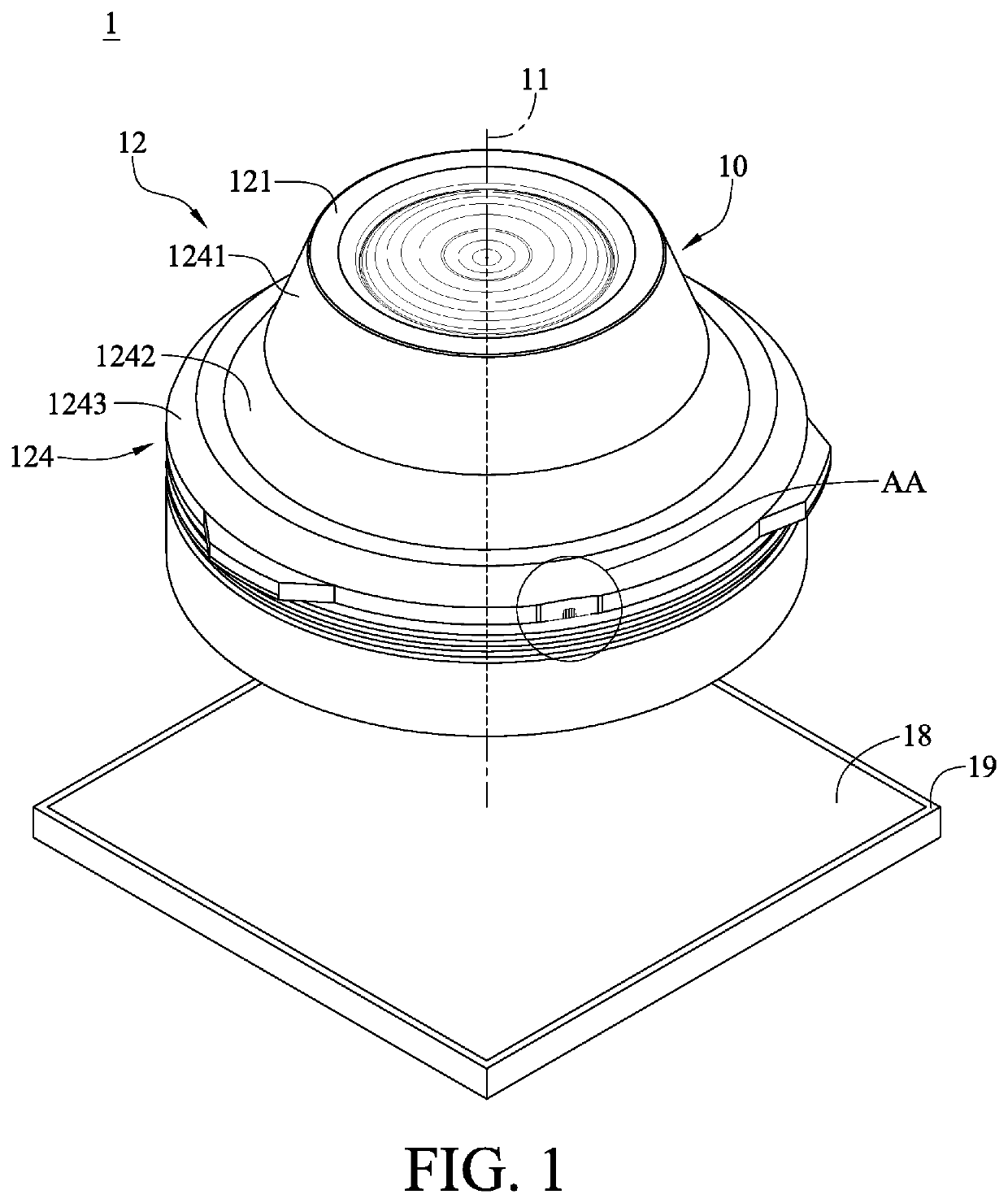
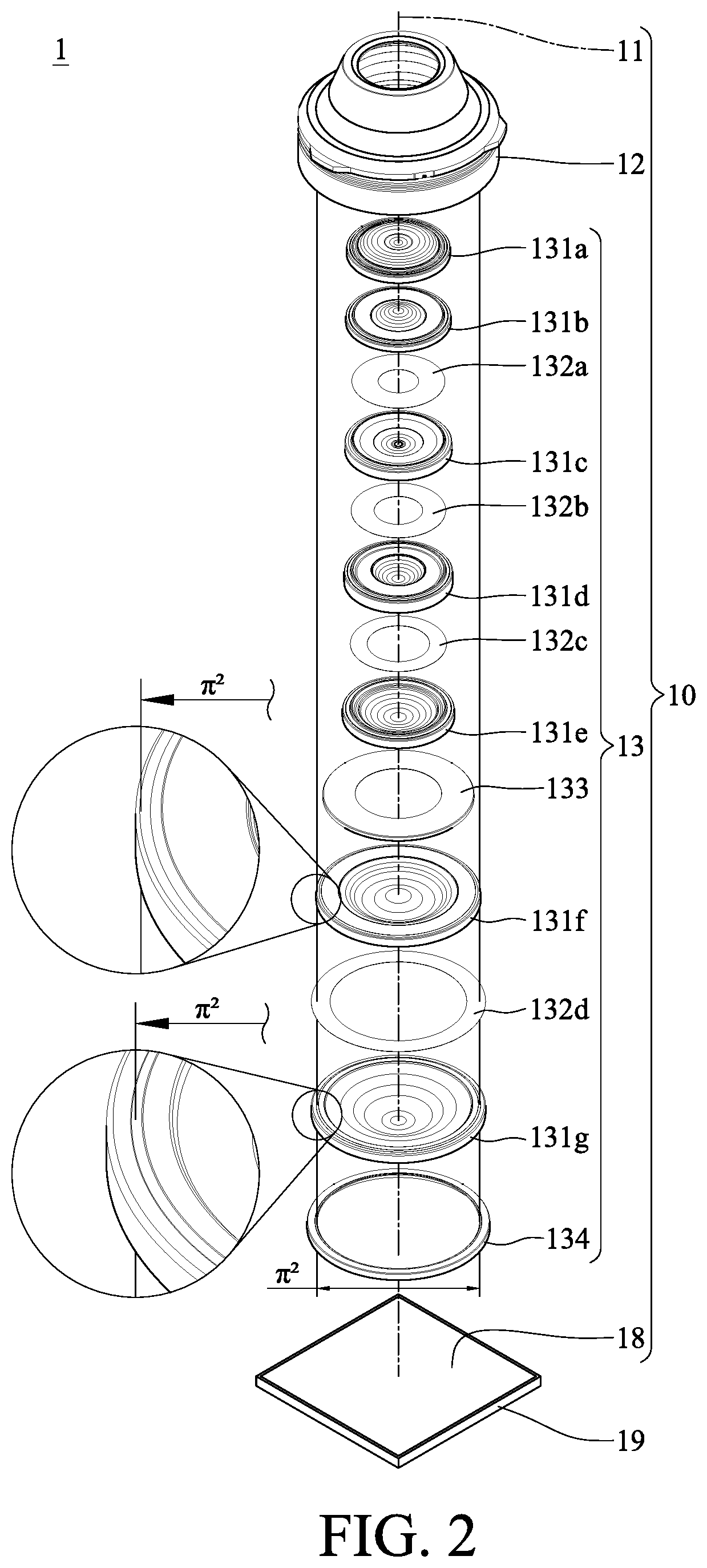
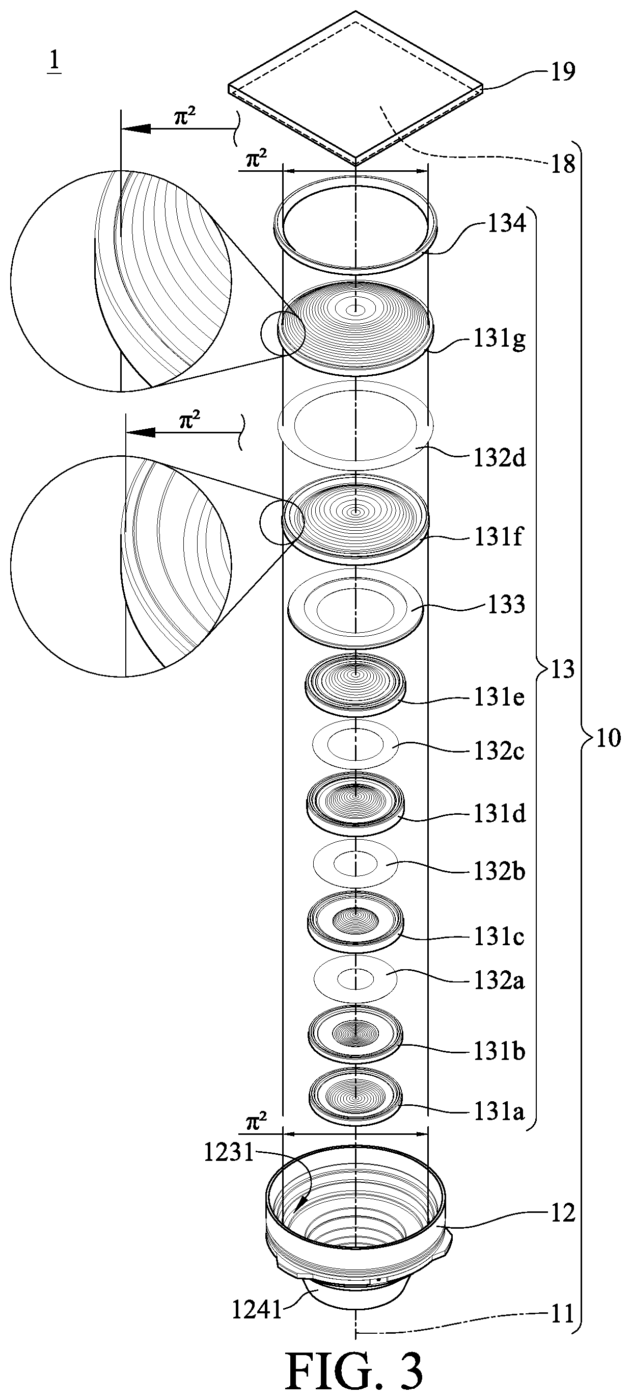
[0075]Please refer to FIG. 1 to FIG. 10, where FIG. 1 is a perspective view of a camera module according to the 1st embodiment of the present disclosure, FIG. 2 is an exploded view of the camera module in FIG. 1, FIG. 3 is another exploded view of the camera module in FIG. 1, FIG. 4 is an enlarged view of the AA region of the camera module in FIG. 1, FIG. 5 is a top view of the camera module in FIG. 1, FIG. 6 is a cross-sectional view of the camera module in FIG. 1, FIG. 7 is an exploded view of the camera module in FIG. 6, FIG. 8 is a schematic view of the injection mold configured for forming the plastic lens barrel of the camera module in FIG. 1 therein, FIG. 9 is a perspective view of showing the plastic material flow direction during the formation of the plastic lens barrel of the camera module in FIG. 1 by injection molding, and FIG. 10 is a perspective view of the sectioned plastic lens barrel in FIG. 9 for showing the plastic material flow direction during the formation.
[007...
2nd embodiment
[0091]Please refer to FIG. 11 to FIG. 17, where FIG. 11 is a perspective view of a camera module according to the 2nd embodiment of the present disclosure, FIG. 12 is an enlarged view of the BB region of the camera module in FIG. 11, FIG. 13 is a top view of the camera module in FIG. 11, FIG. 14 is a cross-sectional view of the camera module in FIG. 11, FIG. 15 is an exploded view of the camera module in FIG. 14, FIG. 16 is a perspective view of showing the plastic material flow direction during the formation of the plastic lens barrel of the camera module in FIG. 11 by injection molding, and FIG. 17 is a perspective view of the sectioned plastic lens barrel in FIG. 16 for showing the plastic material flow direction during the formation. Note that only the differences between this and the previous embodiments are illustrated hereinafter.
[0092]In this embodiment, a camera module 2 includes an imaging lens system 20 and an image sensor 29. The imaging lens system 20 has an optical axi...
3rd embodiment
[0107]Please refer to FIG. 18 to FIG. 24, where FIG. 18 is a perspective view of a camera module according to the 3rd embodiment of the present disclosure, FIG. 19 is an enlarged view of the CC region of the camera module in FIG. 18, FIG. 20 is a top view of the camera module in FIG. 18, FIG. 21 is a cross-sectional view of the camera module in FIG. 18, FIG. 22 is an exploded view of the camera module in FIG. 21, FIG. 23 is a perspective view of showing the plastic material flow direction during the formation of the plastic lens barrel of the camera module in FIG. 18 by injection molding, and FIG. 24 is a perspective view of the sectioned plastic lens barrel in FIG. 23 for showing the plastic material flow direction during the formation. Note that only the differences between this and the previous embodiments are illustrated hereinafter.
[0108]In this embodiment, a camera module 3 includes an imaging lens system 30 and an image sensor 39. The imaging lens system 30 has an optical axi...
PUM
 Abstract
Description
Claims
Application Information
 - R&D Engineer
- R&D Manager
- IP Professional
- Industry Leading Data Capabilities
- Powerful AI technology
- Patent DNA Extraction
Browse by: Latest US Patents, China's latest patents, Technical Efficacy Thesaurus, Application Domain, Technology Topic.
© 2024 PatSnap. All rights reserved.Legal|Privacy policy|Modern Slavery Act Transparency Statement|Sitemap