Eureka AIR delivers breakthrough ideas for toughest innovation challenges, trusted by R&D personnel around the world.

Machining based on strategies selected based on prioritized aspects of manufacturing

a technology of manufacturing strategy and manufacturing strategy, applied in the field of manufacturing, can solve the problems of both cumbersome and time-consuming, test run and/or simulation, cumbersome and time-consuming, etc., and achieve the effect of reducing or solving the drawbacks

Pending Publication Date: 2021-08-12
SANDVIK MACHINING SOLUTIONS AB
View PDF0 Cites 0 Cited by
  • Summary
  • Abstract
  • Description
  • Claims
  • Application Information

AI Technical Summary

Benefits of technology

This patent aims to make it easier to manufacture objects by providing multiple options for how to machine certain features of the object. This reduces the complexity of the manufacturing process planning, resulting in a simpler and more efficient process. The technical effect of this patent is to make manufacturing more easily accessible.

Problems solved by technology

This is a complicated task involving many factors / parameters such as selecting machine tools, operation sequences (for example involving roughing, semi-finishing and finishing), operation strategies, fixtures for holding the work piece, cutting tools, tool paths, and cutting data (such as feed rate, cutting speed, and depth of cut).
This typically involves repeatedly defining a candidate set of factors / parameters and evaluating them in manufacturing simulations, which is both cumbersome and time consuming.
This typically involves repeatedly defining a candidate machine code and evaluating the code in manufacturing simulations, which is both cumbersome and time consuming.
Test runs and / or simulations may for example incur extra costs and / or cause delays.

Method used


Image

  • Machining based on strategies selected based on prioritized aspects of manufacturing
  • Machining based on strategies selected based on prioritized aspects of manufacturing
  • Machining based on strategies selected based on prioritized aspects of manufacturing

Examples


Embodiment Construction

[0024]In the present disclosure the term tool life denotes aspects that affect cutting tool or machine tool expected lifetime. In one example, a longer tool life for a cutting tool can be expected by selecting a small depth of cut and a shorter tool life can be expected by selecting a large depth of cut.

[0025]In the present disclosure the term surface quality denotes manufacturing quality of a geometric feature of an object. In one example, this may be shape accuracy and / or geometric dimensions and / or surface finish tolerances, e.g. defined by product and manufacturing information.

[0026]In the present disclosure the term surface manufacturing speed denotes aspects that affect productivity when manufacturing the object, such as speed of manufacturing or time of manufacturing. In one example, a lower manufacturing speed can be expected by selecting a small depth of cut and a higher manufacturing speed can be expected by selecting a large depth of cut.

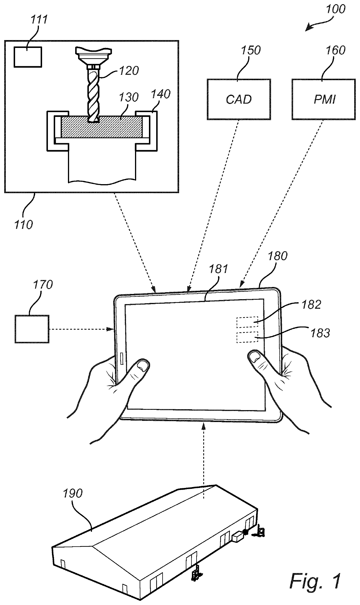
[0027]FIG. 1 is a schematic overvi...


PUM


Abstract

A method includes the steps of receiving user input indicative of prioritized aspects of manufacturing of an object, the prioritized aspects including tool life or surface quality or object manufacturing speed; obtaining a model of an object to be manufactured via subtractive manufacturing; identifying, based on the model, a geometric feature to be machined as part of manufacturing the object; obtaining a plurality of strategies for machining the geometric feature, by accessing a database, the plurality of strategies defining alternative ways of machining the geometric feature; selecting at least one strategy from the plurality of strategies by ranking the plurality of strategies using the prioritized aspects of manufacturing and selecting at least one strategy having the highest ranking, providing, based on the at least one selected strategy, instructions for causing the one or more machine tools to manufacture the object via subtractive manufacturing.

Description

TECHNICAL FIELD[0001]The present disclosure generally relates to machining, and in particular to process planning for machining operations for subtractive manufacturing.BACKGROUND[0002]Computer-aided design (CAD) models or three dimensional, 3D, models are often employed to define objects to be manufactured. Tolerances and other requirements for the objects to be manufactured may also be obtained via product and manufacturing information (PMI). The manufacturing may be performed via machining operations performed by one or more machine tools. A cutting tool mounted in the machine tool is moved by the machine tool relative to a work piece, so that the cutting tool cuts away material from the work piece to form one or more geometric feature of the object to be manufactured.[0003]Computer-aided manufacturing (CAM) is typically employed to decide how to manufacture the object defined by the CAD model. This is a complicated task involving many factors / parameters such as selecting machine...

Claims


Application Information

Patent Timeline
Patent Type & Authority Applications(United States)
IPC IPC(8): G05B19/4099
CPCG05B19/4099G05B2219/35012G05B2219/36252G05B19/40931G05B19/4097G05B19/40937G05B19/4093G05B19/409G05B2219/35168G05B2219/36499G05B2219/42155G05B19/4065G05B2219/36284
Inventor NORDELL, HUGOBRANDT, DANIELWEDLUND, DANIEL
Owner SANDVIK MACHINING SOLUTIONS AB
Why Eureka
Eureka Blog
Learn More