Touch panel and display apparatus including touch panel

Pending Publication Date: 2021-08-12
MITSUBISHI ELECTRIC CORP
View PDF0 Cites 1 Cited by
  • Summary
  • Abstract
  • Description
  • Claims
  • Application Information

AI Technical Summary

Benefits of technology

The patent is about a touch panel that improves sensitivity and tolerance to pressure and static electricity. The panel has two electrodes: one on the cover panel and one on the touch sensor substrate. The second electrode is formed at a corner of the touch sensor substrate, which enhances sensitivity to pressure detection. Additionally, there is a ground electrode on the outer peripheral side of the first electrode on the cover panel, which improves tolerance to static electricity.

Problems solved by technology

In the technology described in Japanese Patent Application Laid-Open No. 2011-028476, when the cover panel is attached, the second substrate and the cover panel need to be deformed at the time of a press, which may cause deterioration of sensitivity of pressure detection.
In addition, two layers of transparent electrodes are formed inside a display region as electrodes that can detect pressure, and thus there is a problem that display performance is deteriorated due to increase of reflectance and reduction of transmittance of the transparent electrodes.
In that case, however, there is more influence received from static electricity and there is a possibility of electrostatic breakdown.

Method used


Image

  • Touch panel and display apparatus including touch panel
  • Touch panel and display apparatus including touch panel
  • Touch panel and display apparatus including touch panel

Examples


first embodiment

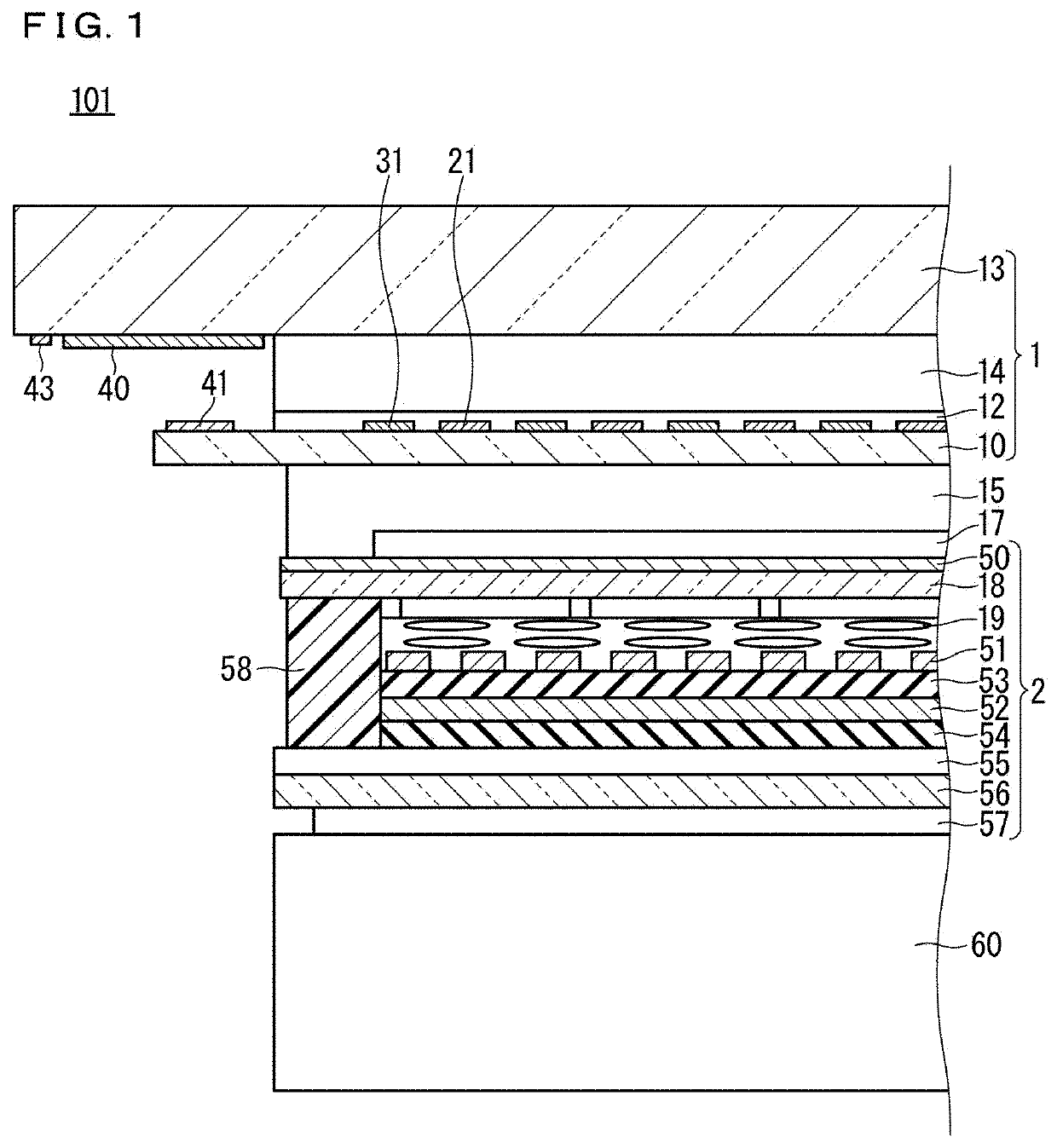
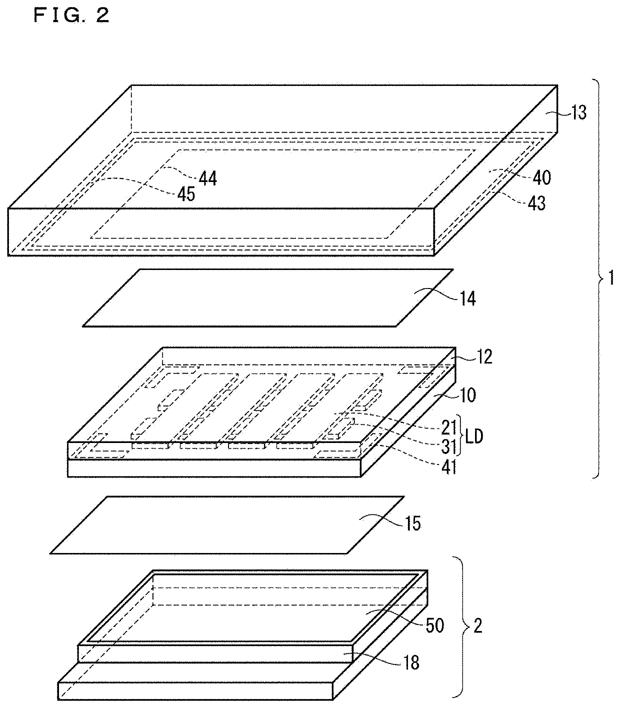
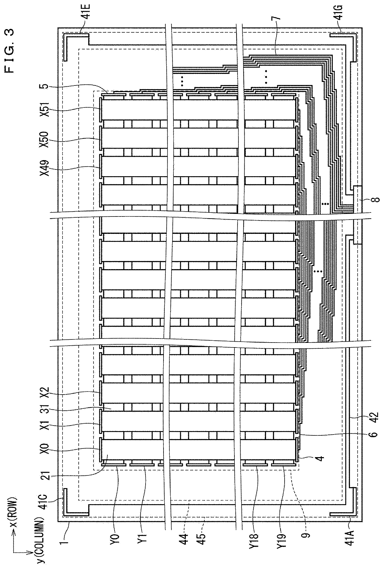
[0025]The first embodiment will be described below with reference to the drawings. FIG. 1 is a partial cross-sectional diagram schematically illustrating a configuration of a display apparatus 101 including a touch panel 1 according to the first embodiment. FIG. 2 is an exploded perspective view schematically illustrating a layer configuration of a front surface side of the display apparatus 101 including the touch panel 1. FIG. 3 is a plan view schematically illustrating a configuration of the touch panel 1. Note that, in FIG. 2, the shape of each member is simplified in illustration.

[0026]As illustrated in FIG. 1, the display apparatus 101 is an apparatus that can identify the position indicated by a pointer such as a finger. The display apparatus 101 includes a touch panel 1, a liquid crystal panel 2, and a backlight unit 60. Note that, in FIG. 1, the backlight unit 60 is simplified in illustration. Further, a metal frame that covers the liquid crystal panel 2 and the backlight u...

second embodiment

[0078]Next, the touch panel 1 and the display apparatus 101 according to the second embodiment will be described. FIG, 9 is an exploded perspective view schematically illustrating a layer configuration of a front surface side of the display apparatus 101 including the touch panel 1 according to the second embodiment. FIG, 10 is a plan view schematically illustrating a configuration of the touch panel 1 according to the second embodiment. FIG. 11 is a diagram illustrating an example of a positional relationship between the second electrode 41 and the first electrode 40 according to the second embodiment. FIG. 12 is a diagram illustrating another example of a positional relationship between the second electrode 41 and the first electrode 40 according to the second embodiment. Note that, in the second embodiment, components the same as those described in the first embodiment are denoted by the same reference signs and description thereof will be omitted.

[0079]As illustrated in FIG. 9 a...

third embodiment

[0090]Next, the touch panel 1 and the display apparatus 101 according to the third embodiment will be described. FIG. 13 is a partial cross-sectional diagram schematically illustrating a configuration of the display apparatus 101 including the touch panel 1 according to the third embodiment. Note that, in the third embodiment, components the same as those described in the first and second embodiments are denoted by the same reference signs and description thereof will be omitted.

[0091]As illustrated in FIG. 13, the third embodiment is different from the first embodiment in the positional relationship between the first electrode 40 and the ground electrode 43, which have a layered structure.

[0092]The touch panel 1 further includes an insulation layer 47 that is formed on a surface of the ground electrode 43 on the opposite side of the cover panel 13. The first electrode 40 is formed on the cover panel 13 with the ground electrode 43 and the insulation layer 47 being interposed thereb...


PUM


Abstract

A touch panel includes a base substrate, a cover panel, a first electrode formed outside of a display region on a back surface of the cover panel, and a second electrode formed outside of the display region on a front surface of the base substrate. A pressure when the base substrate is pressed by the pointer through the cover panel is detected by measuring a change of a distance between the first electrode and the second electrode when the front surface of the cover panel is pressed as a change of electrostatic capacitance between the first electrode and the second electrode. The touch panel further includes a ground electrode formed on an outer peripheral side of the first electrode of the cover panel.

Description

BACKGROUND OF THE INVENTIONField of the Invention[0001]The present disclosure relates to a touch panel and a display apparatus including the touch panel.Description of the Background Art[0002]In recent years, display apparatuses including a touch panel have been used. The touch panel is an apparatus that identities a position touched by a pointer such as a finger. The touch panel has been attracting attention as one of excellent user interface (UI) means. Touch panels of various methods, such as a resistive film method and an electrostatic capacitance method have been made into products.[0003]As one touch panel of the electrostatic capacitance method, there is a touch panel of a projected capacitive method (see, for example, Japanese Patent Application Laid-Open No. 2012-103761). According to the projected capacitive method, touch can be detected even when a front surface side of sensors incorporated into the touch panel is covered by a protective plate such as a glass plate having ...

Claims


Application Information

Patent Timeline
IPC IPC(8): G06F3/044
CPCG06F3/0447G06F3/0446G06F3/0412G06F3/0418G06F3/0448
Inventor MIYAHARA, KAGEYASUMORI, SEIICHIROSHIMASAKI, YUSUKEONO, TAKESHIORITA, TAE
Owner MITSUBISHI ELECTRIC CORP
Why Eureka
Try Eureka