Method of controlling a haircare appliance

a haircare appliance and control method technology, applied in the field of haircare appliances, can solve the problems of large overshoot and large time delay of desired temperature, and achieve the effect of more and accurate predicted heater trace temperatur

Pending Publication Date: 2021-08-19
DYSON TECH LTD
View PDF0 Cites 0 Cited by
  • Summary
  • Abstract
  • Description
  • Claims
  • Application Information

AI Technical Summary

Benefits of technology

[0018]The heater may comprise a heat sink, and predicting a predicted heater trace temperature may comprise using a measured heat sink temperature. This may be beneficial over, for example, using the measured output air temperature, as the airflow may impact on the accuracy of the temperature measurement, and so using a measured heat sink temperature may provide a more accurate predicted heater trace temperature.
[0019]The heater may comprise a ceramic plate to which the heater trace is attached, and predicting a predicted heater trace temperature may comprise using a measured ceramic plate temperature. This may be beneficial over, for example, using the measured air output temperature, as the airflow may impact on the accuracy of the temperature measurement, and so using a measured ceramic plate temperature may provide a more accurate predicted heater trace temperature. Furthermore, the ceramic plate may comprise a pre-existing temperature sensor, for example for thermal safety reasons, and hence using a measured ceramic plate temperature may provide a more accurate predicted heater trace temperature without incurring the cost and/or complexity of an additional temperature sensor.
[0020]The heater may comprise a plurality of heater traces, and the method may comprise determining a desired average heater trace temperature based on the comparison of the measured output air temperature to the desired output air temperature, predicting a predicted average heater trace temperature, comparing the predicted average heater trace temperature to the desired average heater trace temperature, and outputting a control signal based on the comparison of the predicted average heater trace temperature to the desired average heater trace temperature. Predicting a predicted average heater trace tempera

Problems solved by technology

Where a control signal is output solely based on a comparison of a measured output temperature to a desired output temperature, there may be a lar

Method used


Image

  • Method of controlling a haircare appliance
  • Method of controlling a haircare appliance
  • Method of controlling a haircare appliance

Examples


Embodiment Construction

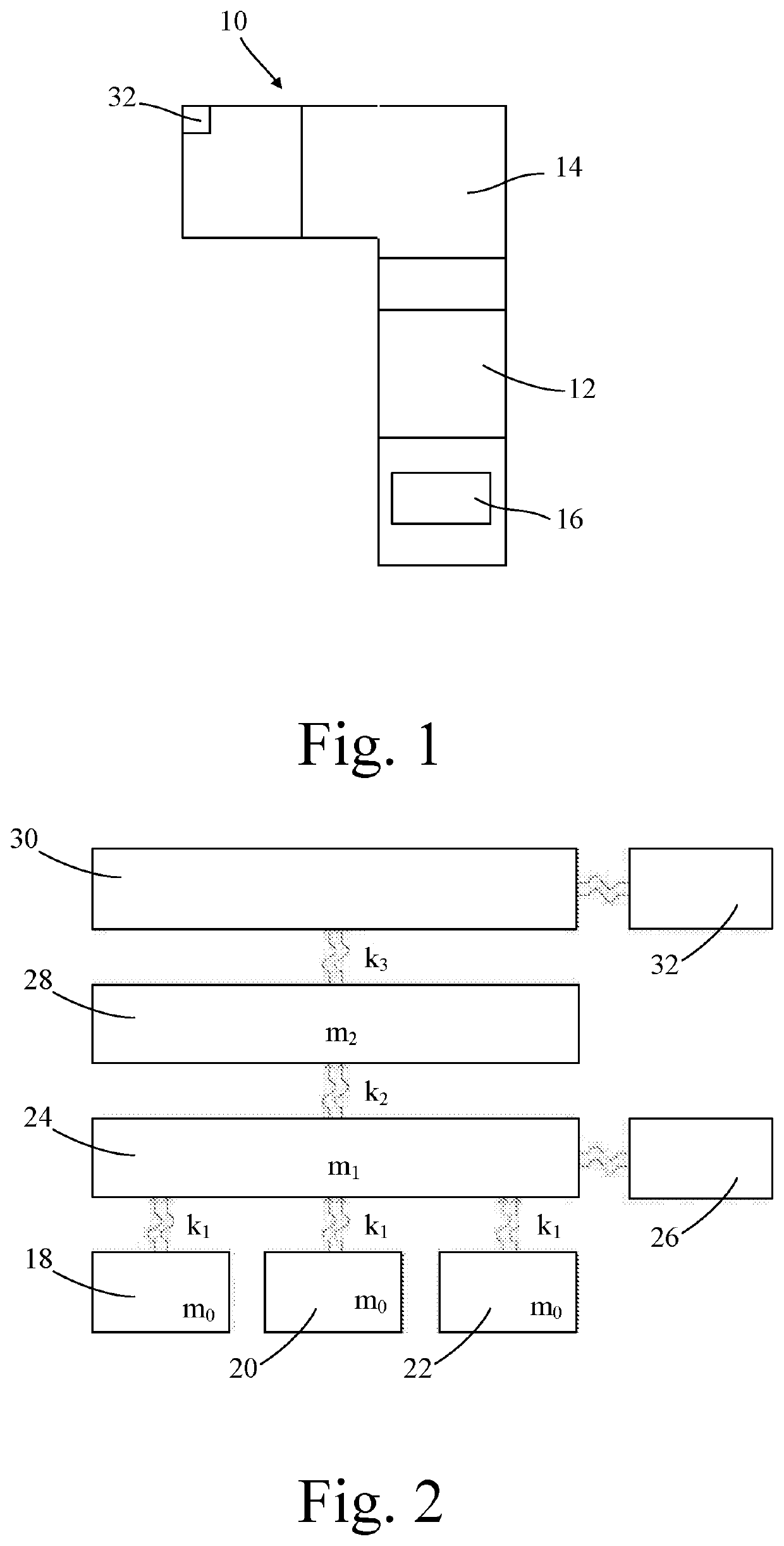
[0042]A haircare appliance, in the form of a hairdryer, generally designated 10, is shown schematically in FIG. 1. The hairdryer 10 comprises a motor 12, a heater 14, and a controller 16. Details of the motor 12 are not pertinent to the present invention, and will not be included here for the sake of brevity, save to say that the motor 12 generates airflow through the hairdryer 10 in use. A suitable motor 12 may, for example, be the motor disclosed in published PCT patent application WO2017 / 098200.

[0043]The heater 14 is shown schematically in isolation in FIG. 2, and comprises three heater traces 18,20,22, a ceramic heater plate 24, a resistance temperature detector (RTD) 26, and a heat sink 28. The three heater traces 18,20,22 are formed of tungsten, and sit on the ceramic heater plate 24. The RTD 26 is connected to the ceramic heater plate 24, such that the RTD 26 is able to provide a measure of the temperature of the ceramic heater plate 24 in use. The RTD 26 may also be used as ...


PUM


Abstract

Disclosed herein is a method of controlling a haircare appliance including a heater. The method includes measuring a temperature of output air of the haircare appliance to obtain a measured output air temperature. The method includes comparing the measured output air temperature to a desired output air temperature. The method includes determining a desired heater temperature based on the comparison of the measured output air temperature to the desired output air temperature. The method includes predicting a predicted heater temperature. The method includes comparing the predicted heater temperature to the desired heater temperature. The method includes outputting a control signal based on the comparison of the predicted heater temperature to the desired heater temperature.

Description

REFERENCE TO RELATED APPLICATIONS[0001]This application is a national phase application under 35 USC 371 of International Application No. PCT / GB2019 / 052473, filed Sep. 5, 2019, which claims the priority of United Kingdom Application No. 1814658.9, filed Sep. 10, 2018, the entire contents of each of which are incorporated herein by reference.FIELD OF THE DISCLOSURE[0002]The present invention relates to a method of controlling a haircare appliance, and more particularly to a method of controlling a haircare appliance comprising a heater.BACKGROUND OF THE DISCLOSURE[0003]Haircare appliances, for example hairdryers or hot styling brushes, typically comprise a heater for heating air flowing through the appliance. It has previously been proposed to control the heater of a haircare appliance such that the temperature of air output by the appliance is kept at a desired level.SUMMARY OF THE DISCLOSURE[0004]According to a first aspect of the present invention there is provided a method of con...

Claims


Application Information

Patent Timeline
IPC IPC(8): A45D20/08
CPCA45D20/08A45D2200/15A45D20/12A45D20/30
Inventor LOKE, SIEW LINGNIU, LI
Owner DYSON TECH LTD
Why Eureka
Try Eureka