Self-piercing rivet fastening device

Active Publication Date: 2021-08-19
NEWFREY
View PDF0 Cites 0 Cited by
  • Summary
  • Abstract
  • Description
  • Claims
  • Application Information

AI Technical Summary

Benefits of technology

[0016]According to the present invention, it is possible to provide a rivet fastening

Problems solved by technology

Further, an expansion load is applied to the O-ring, and after a certain number of uses, the O-ring is torn and broken at the edge of the mounting groove of the O-ring.
Since the collet is stored

Method used


Image

  • Self-piercing rivet fastening device
  • Self-piercing rivet fastening device
  • Self-piercing rivet fastening device

Examples


Embodiment Construction

[0022]Hereinafter, embodiments for carrying out the present invention will be described with reference to the accompanying drawings. By assigning the same or similar reference numbers to the same or similar members, duplicate description will be omitted. In order to explain the present invention in an easily understandable manner, the scale of the drawings is not consistent.

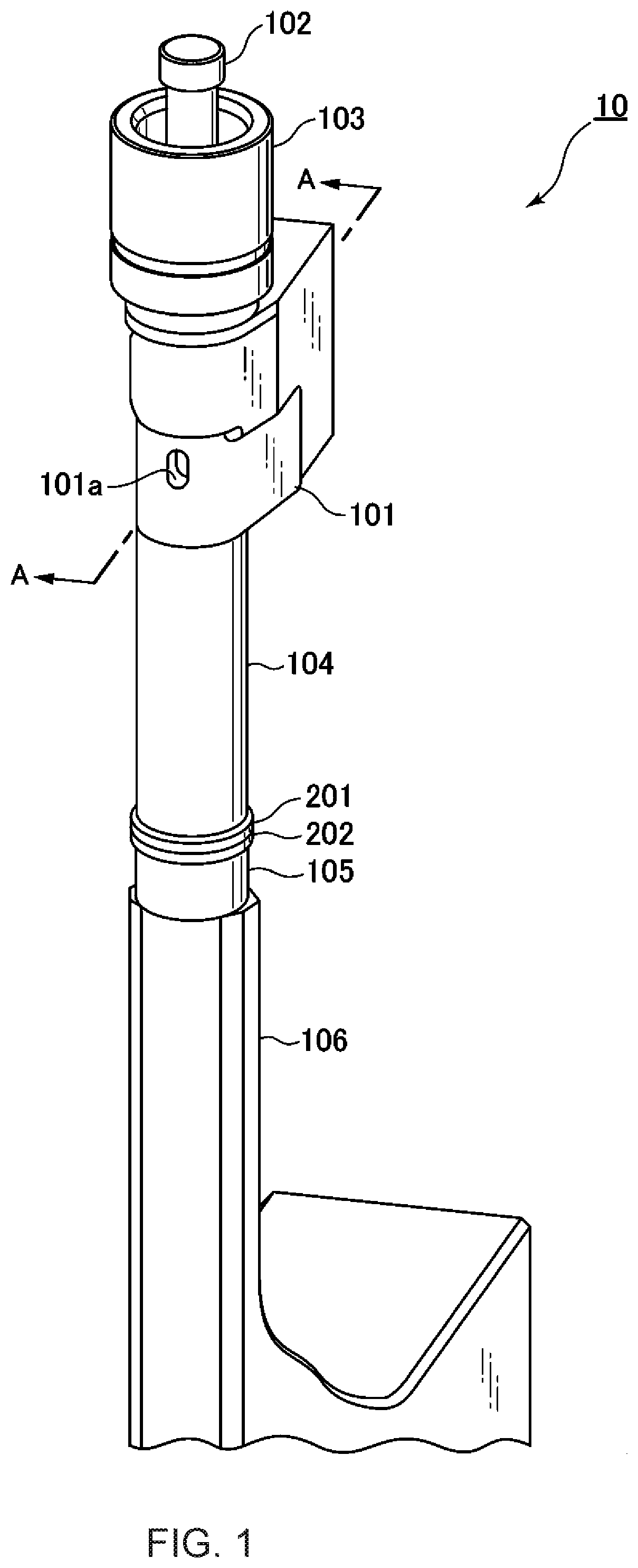
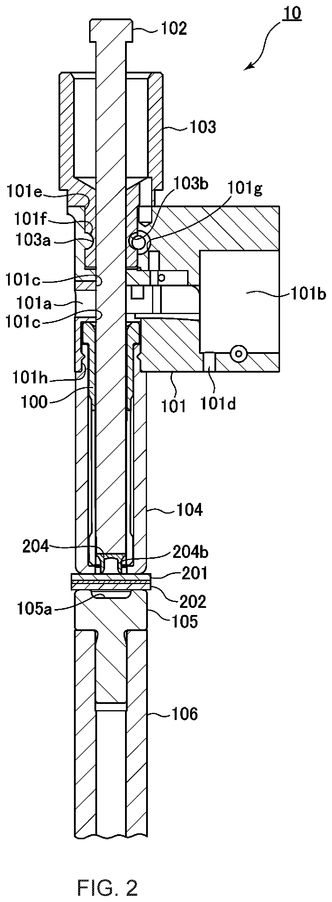
[0023]The configuration of the system 10 for feeding and fastening rivets will be described with reference to FIGS. 1 and 2.

[0024]FIG. 1 is a partial perspective view of a portion where a member to be fastened is held by a system 10 for feeding and fastening rivets, and FIG. 2 is a cross-section view taken along line A-A of FIG. 1.

[0025]As shown in FIG. 1, the system 10 has a receiver 101 that receives self-piercing rivets (SPR) supplied one by one from a rivet feeder, a punch 102 for driving the supplied SPR, a punch holder 103 that slidably holds the punch 102, a nose piece 104 that protects the linear motion w...


PUM

PropertyMeasurementUnit
Lengthaaaaaaaaaa
Thicknessaaaaaaaaaa
Angleaaaaaaaaaa

Abstract

A collet to feed and fasten cylindrical rivets includes an inlet unit that accepts and supports the rivet, a first feeding unit connected from the inlet unit and configured to feed the rivet, a second feeding unit connected to the first feeding unit opposite to the inlet unit and configured to feed the rivet, and an outlet unit that is connected to the second feeding unit opposite to the first feeding unit and supports the rivet that is fed to it. The inlet unit and the first feeding unit have at least two first slots at opposite angles, the second feeding unit and the outlet unit have more of second slots than the first slots , and when the rivet enters the first feeding unit, the second slots are closed by the opening of the first slots.

Description

CROSS-REFERENCE TO RELATED APPLICATIONS[0001]This application claims priority from Japanese Patent Application No. 2020-026325, filed on Feb. 19, 2020 the entire disclosure of which is incorporated herein by reference.BACKGROUND OF THE PRESENT INVENTION[0002]The present disclosure relates to a device for feeding and fastening a self-piercing rivet (SPR), and particularly to a collet for feeding and fastening an SPR.[0003]In recent years, a technique for mechanically joining a base metal using SPR has been used as an alternative technique to a direct joining technique such as spot welding. An SPR is a semi-cylindrical rivet having a chevron or dish-shaped head and semi-cylindrical legs forming a cavity beneath the head. The SPR is driven by the following procedure. First, the upper plate (for example, an aluminum plate) and the lower plate (for example, a high-strength steel plate) to be joined are clamped by the die and the nose piece of the fastening device. When the SPR provided i...

Claims


Application Information

Patent Timeline
IPC IPC(8): B21J15/32B21J15/02
CPCB21J15/32B21J15/025B21J15/10B21J15/30B21J15/34B21J15/36B21J15/38B21J15/42B23P19/006F16B2/04F16B19/02B21J15/386B21J15/022B21J15/16B23B2231/2091
Inventor MIZUKAWA, NORIKOMAKINO, HIROYOMIURA, DAISUKE
Owner NEWFREY
Why Eureka
Try Eureka