Battery pack and production method for battery pack

a battery pack and production method technology, applied in the field of batteries, can solve the problems of high-rate performance deterioration, increased contamination, self-confinement due to shrinking the electrode assembly by the negative pressure, etc., and achieve the effect of high high-rate resistan

Active Publication Date: 2021-08-19
TOYOTA JIDOSHA KK
View PDF5 Cites 1 Cited by
  • Summary
  • Abstract
  • Description
  • Claims
  • Application Information

AI Technical Summary

Benefits of technology

[0009]The present disclosure was devised to solve these problems, and an object of the present disclosure is to provide a technique capable of suitably removing a negative pressure within a single cell included in a battery pack for suitably preventing deterioration of high-rate performance otherwise caused by outflow of an electrolyte to the outside of an electrode assembly.
[0011]The battery pack disclosed herein includes the internal pressure adjusting bag disposed inside the battery case and filled with the gas, and the gas supplying device for supplying the gas held in the internal pressure adjusting bag to the internal space of the battery case having been sealed. Thus, a negative pressure within the battery case can be removed after sealing the battery case, and hence deterioration of electrolyte retention within the electrode assembly otherwise caused by self-confinement can be prevented. In addition, in the battery pack having the aforementioned structure, the spacer having the convex rib is used to form the non-confined region forming an electrolyte holding space within the electrode assembly, and the internal pressure adjusting bag is disposed in a region including the non-confined region. Therefore, the electrolyte retention in the non-confined region can be sufficiently assured. Accordingly, in the battery pack disclosed herein, a negative pressure within the single cell included in the battery pack can be suitably removed, and deterioration of high-rate performance otherwise caused by outflow of the electrolyte to the outside of the electrode assembly can be more suitably prevented.
[0021]Thus, the gas supplied from the internal pressure adjusting bag can be prevented from deteriorating battery performance
[0023]Thus, the gas supplied from the internal pressure adjusting bag can be prevented from deteriorating battery performance
[0025]When the confined region is thus formed in both edge portions in the width direction of the core part, the electrolyte can be inhibited from flowing out of the core part where charge / discharge is mainly performed, and hence, the deterioration of the high-rate performance can be more suitably prevented.
[0027]In the production method described above, the internal pressure adjusting bag is disposed in the non-confined region within the battery case in the housing step, and the gas is supplied from the internal pressure adjusting bag after the cell forming step. Thus, a negative pressure in the vicinity of the confined region within the battery case having been sealed can be removed, and hence, the electrolyte is more suitably prevented from flowing out of the electrode assembly. As a result, according to the production method disclosed herein, a battery pack having high high-rate resistance can be produced.

Problems solved by technology

As a result, concentration unevenness of a charge carrier and electrolyte shortage occur within the electrode assembly, and there is a risk that high-rate performance may be deteriorated.
At this point, if the battery case is sealed without removing a negative pressure after the injection of the electrolyte, self-confinement due to shrinking the electrode assembly by the negative pressure occurs.
Besides, the negative pressure can be removed by leaving the battery case opened, after the injection of the electrolyte, for a long period of time (of about 1 hour), but possibilities of production efficiency deterioration and contamination are increased, and hence this method is difficult to employ in the actual production process.

Method used


Image

  • Battery pack and production method for battery pack
  • Battery pack and production method for battery pack
  • Battery pack and production method for battery pack

Examples


first embodiment

1. First Embodiment

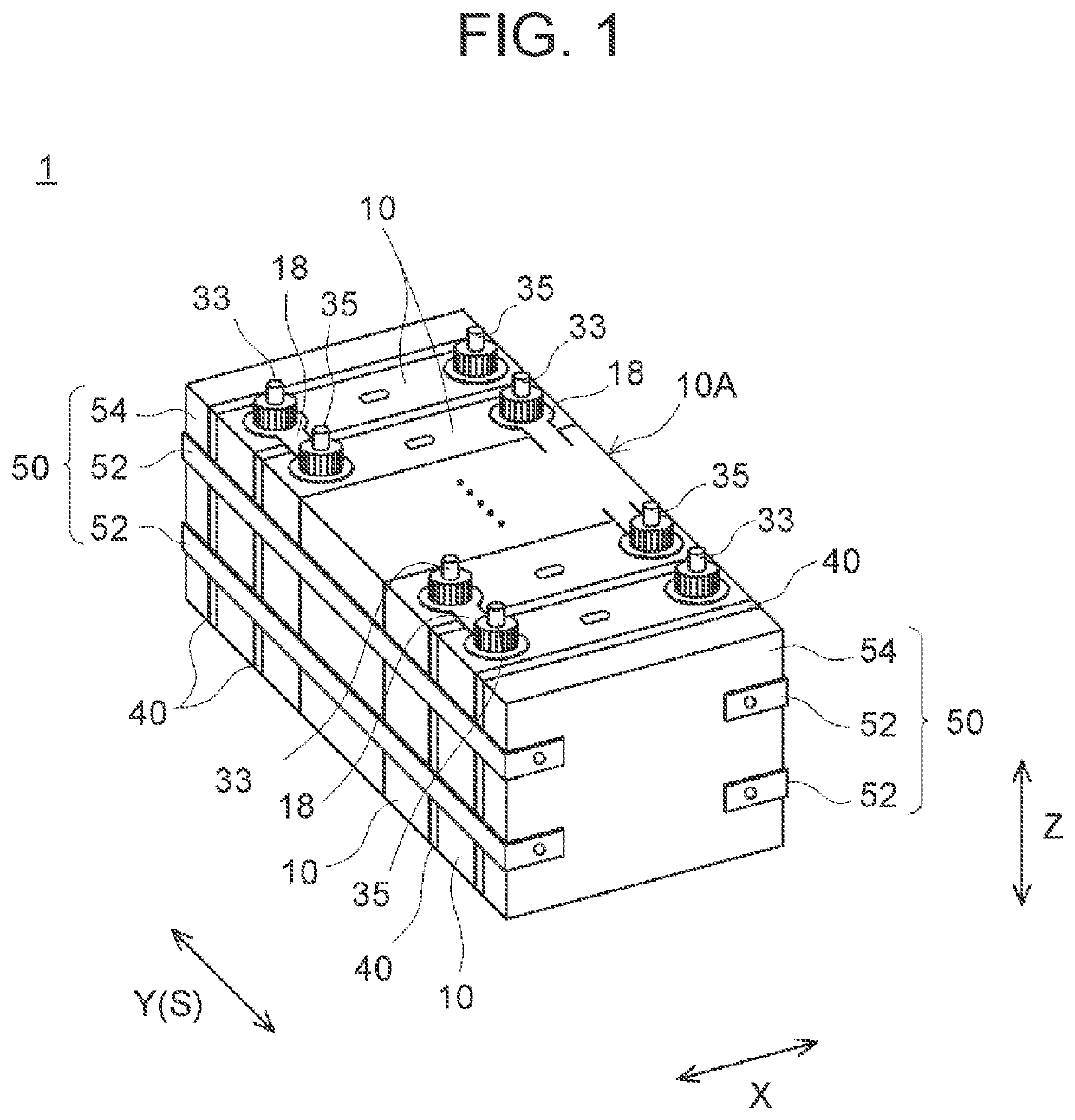
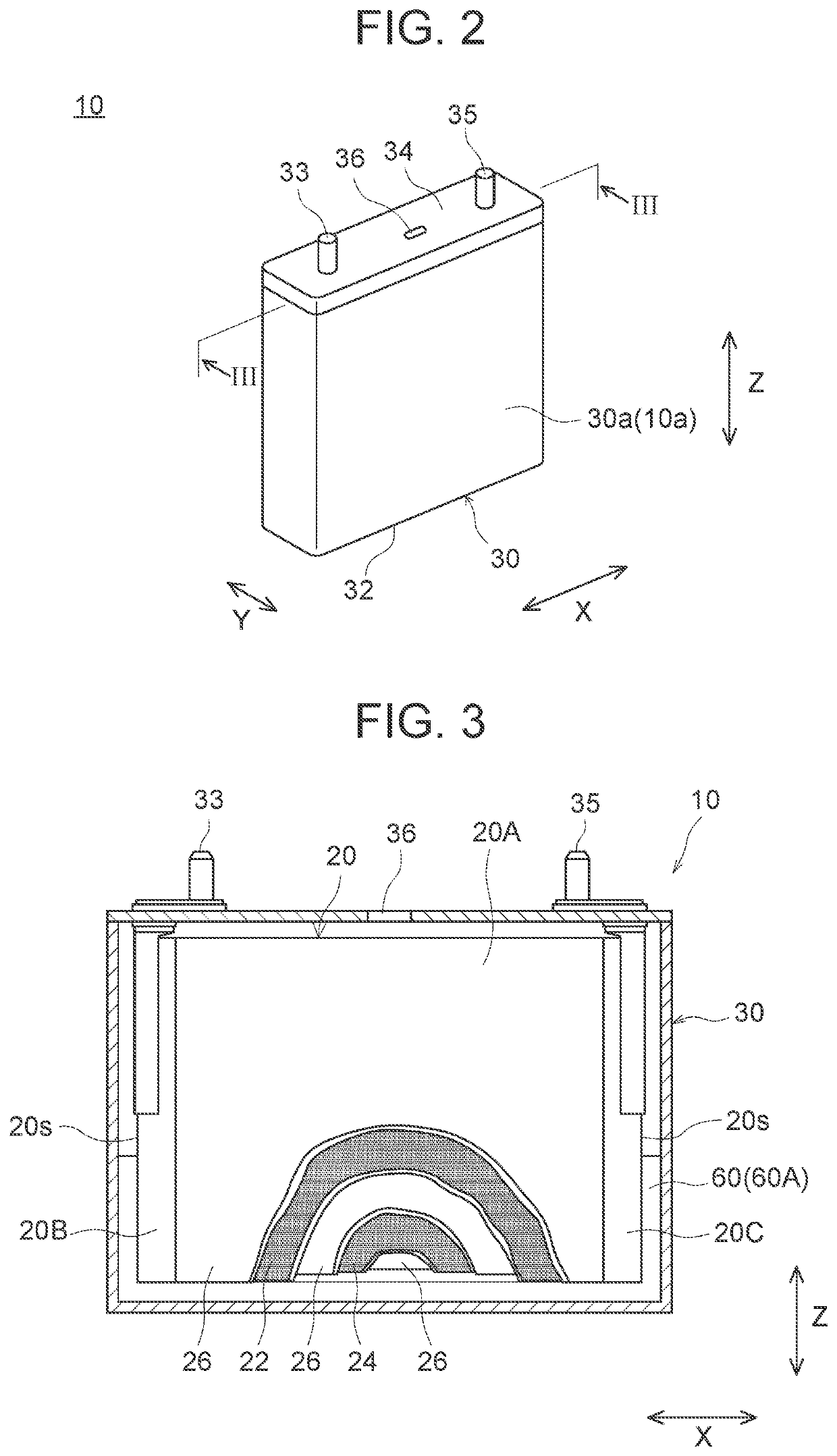
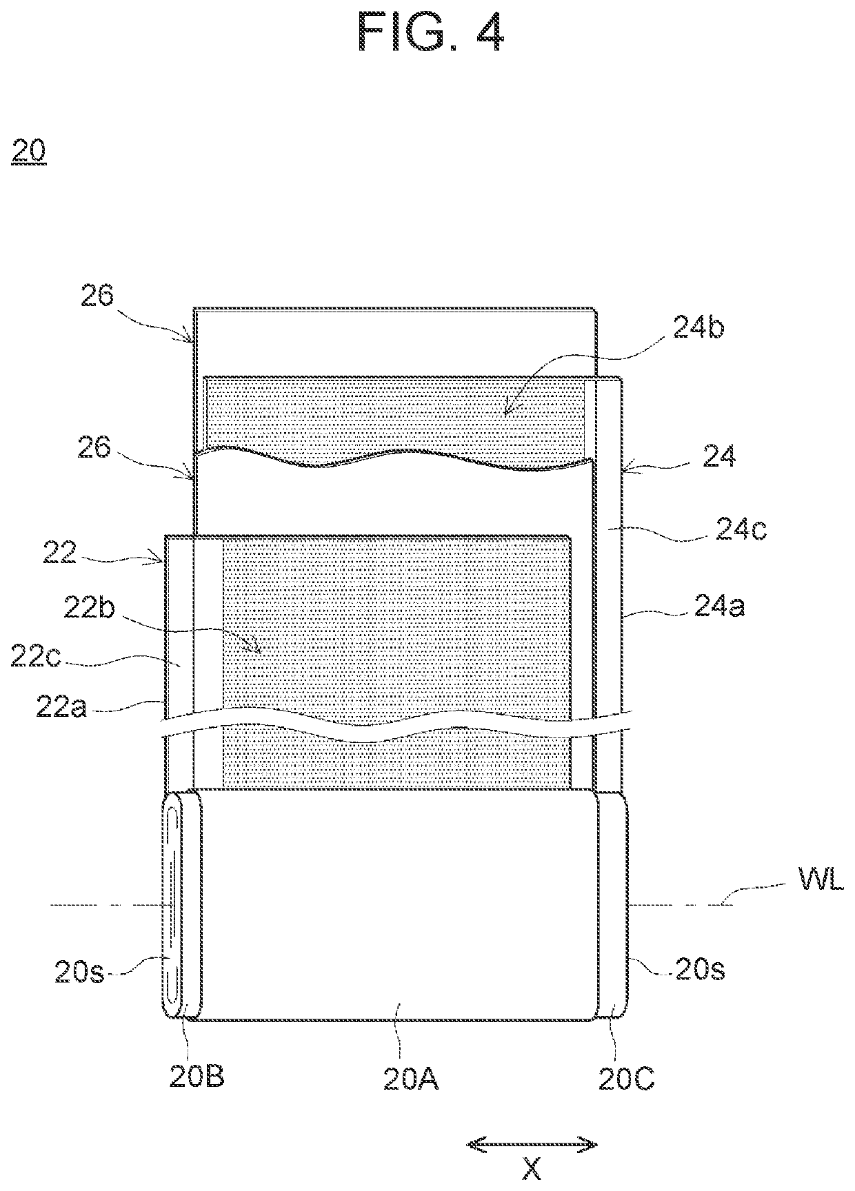
[0053]FIG. 1 is a perspective view schematically illustrating a battery pack according to the first embodiment. FIG. 2 is a perspective view schematically illustrating a single cell of FIG. 1. FIG. 3 is a vertical cross-sectional view taken on line of FIG. 2. FIG. 4 is a perspective view schematically illustrating an electrode assembly of FIG. 3. FIG. 5 is a vertical cross-sectional view taken on an alignment direction of the battery pack according to the first embodiment.

(1) Overall Structure of Battery Pack

[0054]First, the overall structure of the battery pack 1 of the present embodiment will be described. As illustrated in FIG. 1, in the battery pack 1 of the present embodiment, a plurality of single cells 10 are aligned along a prescribed alignment direction S, and the respective single cells 10 are confined along the alignment direction S. In other words, the battery pack 1 of the present embodiment includes a cell group 10A where the plurality of single cell...

second embodiment

(1) Second Embodiment

[0079]FIG. 7 is a vertical cross-sectional view taken on an alignment direction of a battery pack according to the second embodiment. Gas supplying means of the present embodiment is a gas permeable part 74 formed from a material having gas permeability. An internal pressure adjusting bag 70 including this gas permeable part 74 continuously gradually supplies a gas through the gas permeable part74. Thus, the internal pressure of a battery case 30 having been sealed is gradually increased, and hence, a negative pressure within the battery case 30 can be removed before the battery pack 1 is distributed / used.

[0080]Besides, when the gas permeable part 74 is formed as the gas supplying means as in the present embodiment, it is preferable to perform an aging step after the production of a single cell 10 for retaining the single cell 10 for a prescribed period of time under a high temperature environment. Thus, the gas supply through the gas permeable part 74 is accele...

third embodiment

(2) Third Embodiment

[0083]FIG. 8 is a vertical cross-sectional view taken on an alignment direction of a battery pack according to the third embodiment. The battery pack 1 of the present embodiment includes, as gas supplying means, a projection 26a having a sharp tip formed on an outer surface 20a of an electrode assembly 20 facing an internal pressure adjusting bag 70. Specifically, a separator 26 is disposed on an outer surface of an electrode assembly 20 of a general nonaqueous electrolyte secondary battery for preventing a positive electrode mixture layer 22b and a negative electrode mixture layer 24b (see FIG. 4) from dropping off. Since the outer surface 20a of the electrode assembly 20 constructed by the separator 26 does not make contribution to a charge / discharge reaction, a member in a desired shape can be easily formed as the outer surface. When the projection 26a having a sharp tip is formed on the outer surface 20a of the electrode assembly 20 to allow the projection 26...


PUM

PropertyMeasurementUnit
pressureaaaaaaaaaa
pressureaaaaaaaaaa
pressureaaaaaaaaaa

Abstract

In a battery pack disclosed herein, a plurality of single cells are aligned in an alignment direction. In this battery pack, a spacer is disposed in a gap between adjacent ones of the single cells, and a convex rib is formed on the spacer. In a flat surface of each single cell, a region where the rib is in contact is a confined region, and a region where the rib is not in contact is a non-confined region. In the non-confined region within the battery case, an internal pressure adjusting bag filled with a gas is housed. In addition, gas supplying means (soluble part) for supplying the gas held in the internal pressure adjusting bag to an internal space of the battery case is provided. Thus, a negative pressure within the single cell is removed, and deterioration of high-rate performance otherwise caused by outflow of an electrolyte can be prevented.

Description

CROSS-REFERENCE TO RELATED APPLICATION[0001]This application claims priority to Japanese Patent Application No. 2020-026128 filed on Feb. 19, 2020, incorporated herein by reference in its entirety.BACKGROUND1. Technical Field[0002]The disclosure relates to a battery pack and a production method for the same. Specifically, it relates to a battery pack including a plurality of nonaqueous electrolyte secondary batteries each as a single cell, and a method for producing the battery pack.2. Description of Related Art[0003]In recent years, nonaqueous electrolyte secondary batteries (such as lithium ion secondary batteries) have been used as portable power sources for personal computers, mobile devices and the like, and as power supplies for driving various vehicles such as an electric vehicle (EV), a hybrid vehicle (HV), and a plug-in hybrid vehicle (PHV), and the like. Such a nonaqueous electrolyte secondary battery has, for example, a structure in which an electrode assembly including a...

Claims


Application Information

Patent Timeline
Patent Type & Authority Applications(United States)
IPC IPC(8): H01M10/0566H01M10/04H01M10/647H01M50/204H01M50/40H01M4/13
CPCH01M10/0566H01M10/0431H01M4/13H01M50/204H01M50/40H01M10/647H01M10/0525H01M10/0587H01M10/613H01M10/653H01M10/6554H01M50/103H01M50/291H01M50/209H01M10/0468H01M50/609H01M10/04Y02P70/50Y02E60/10
Inventor KOBAYASHI, KEIICHIRO
Owner TOYOTA JIDOSHA KK
Why Eureka
Try Eureka