Devices, facilities, methods and compositions for carbon dioxide capture, sequestration and utilization

a technology of carbon dioxide and carbon dioxide storage, applied in the field of carbon dioxide capture, sequestration and utilization, to achieve the effect of increasing the amount of photosynthetic conversion and achieving the effect of greater surface area-to-volume practicalities

Inactive Publication Date: 2021-08-26
CO2AT LTD
View PDF0 Cites 1 Cited by
  • Summary
  • Abstract
  • Description
  • Claims
  • Application Information

AI Technical Summary

Benefits of technology

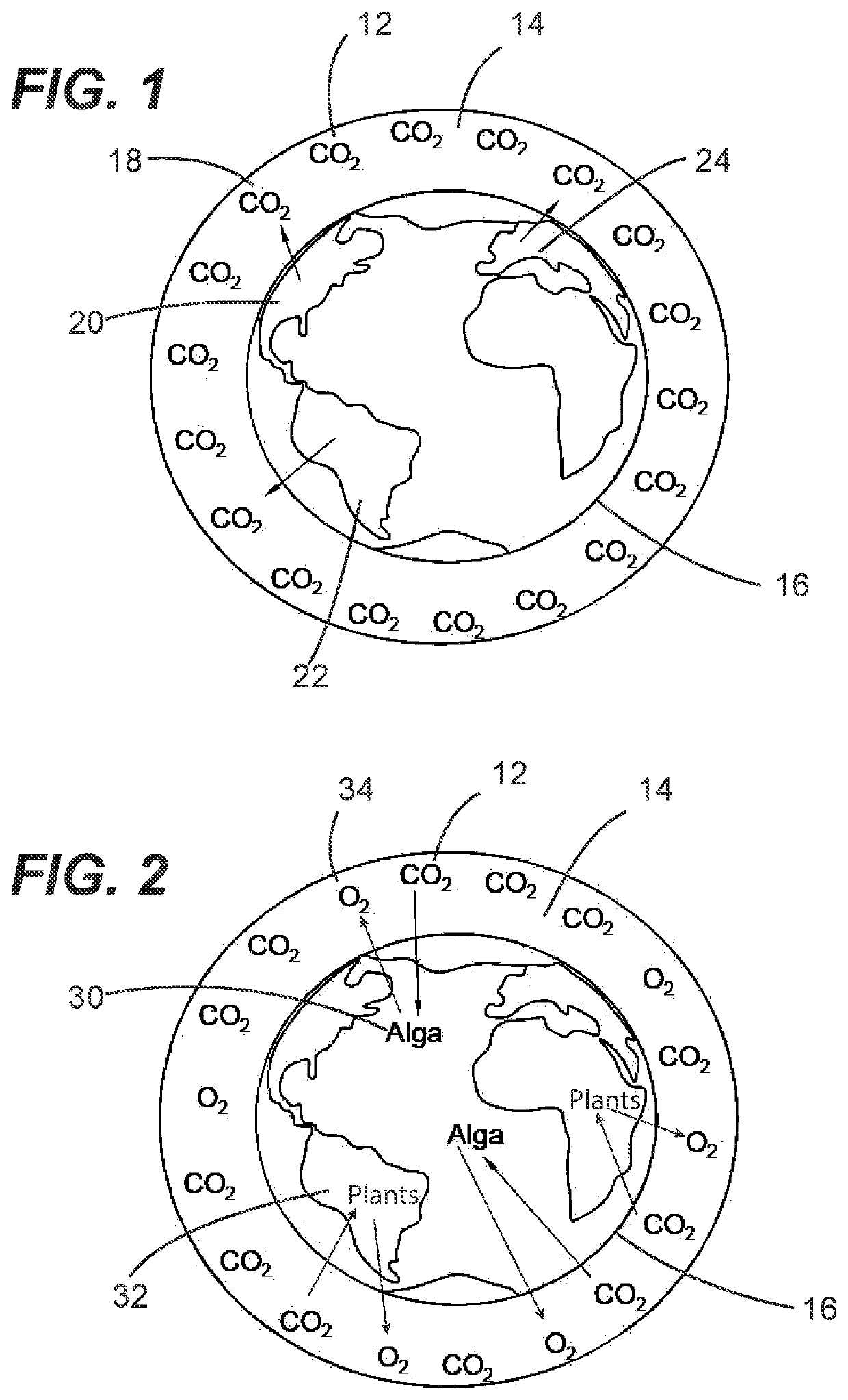
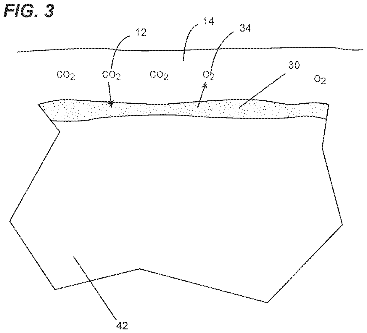
[0010]Embodiments of the present invention are directed to a negative emissions technology that simulates the efficiency and effectiveness of naturally-occurring sources of photosynthesis (e.g., ocean-bound algae and / or terrestrial plants) in a manner that provides for markedly greater surface area-to-volume practicalities. More specifically, embodiments of the present invention comprise photosynthetic organism-containing polymeric materials (e.g., coatings) adapted for being formed on surfaces of vertically extending substrates (i.e., algae-coated vertical surfaces). In one or more embodiments, algae are a preferred photosynthetic organism. In one or more embodiments, the vertically extending substrates can be located within an interior space of a carbon dioxide capture facility in accordance with embodiments of the present invention, which is also referred to herein as a vertical algae farm or forest. The carbon dioxide capture facility can be adapted for providing environmental conditions within the interior space thereof that are conducive to the life, growth and carbon capture of the photosynthetic organism. Advantageously, on a unit-volume basis, a carbon dioxide capture facility in accordance with one of more embodiments of the present invention provides a total area of photosynthetic organism-coated vertical surfaces magnitudes of order greater than the atmosphere-exposed surface of a corresponding volume of ocean or forest. In this manner, embodiments of the present invention enable a marked increase in the amount of photosynthetic conversion of carbon dioxide for a given volume of space as compared to ocean-bound algae or terrestrial plants and, thus, advantageously overcome shortcomings associated with other negative emission technologies.
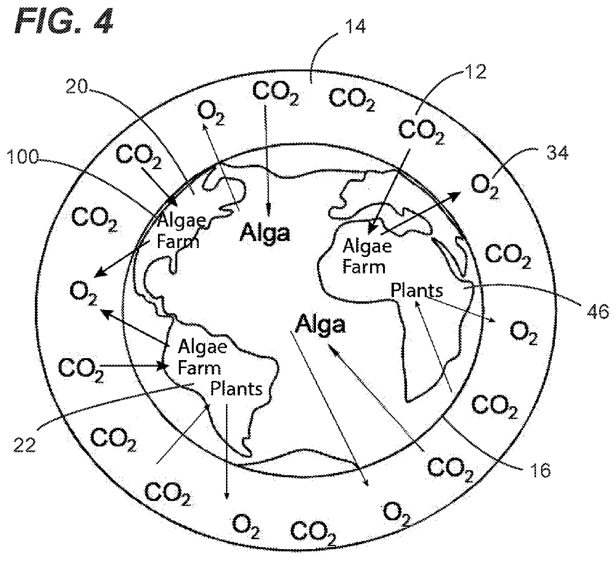
[0012]In one embodiment of the present invention, a carbon dioxide capture facility is provided in the form of an algae farm (or forest). The algae farm provides photosynthetic capture of carbon dioxide from air surrounding the Earth (i.e., atmospheric carbon dioxide) with a resulting release of oxygen into the atmosphere. Each algae farm (or forest) is an example of a carbon dioxide capture facility configured in accordance with one or more embodiments of the present invention. Each algae farm comprises algae-containing coating on surface area of a coating substrate. Through exposure to air, light and water, the algae-containing coating provides naturally-occurring photosynthetic conversion of atmospheric carbon dioxide (CO2) within the air. Such photosynthetic conversion results in the production of oxygen and carbon-containing by-product (i.e., carbohydrate such as saccharide). The oxygen is delivered from the algae farm back into the air and the carbon-containing by-product can be utilized and / or sequestered (i.e., stored) such as, for example, by delivery into the earth (e.g., deep well, storage cavern, etc.), by delivery into subsea environment, and / or utilization in the production of products (e.g., building products, fuels, food stocks, and the like). Accordingly, the algae farm can advantageously provide a volumetric efficiency (and associated terrestrial footprint) and that provides a marked increase in the amount of photosynthetic conversion of carbon dioxide for a given volume of space as compared to naturally-occurring sources of photosynthesis (e.g., ocean-bound algae and / or terrestrial plants).
[0013]In another embodiment of the present invention, a carbon dioxide capture device comprises one or more coating substrates that are each in the form of a generally planar shaped article (e.g., a sheet of material), wherein at least one side of each coating substrate is coated with a photosynthetic organism containing coating. Carbon-containing by-product is generated by the photosynthetic organism containing coating. The carbon dioxide capture devices are configured for being arranged within an interior space of an encasement of a carbon dioxide capture facility and / or carbon dioxide capture apparatus in a manner that provides sufficient space for the photosynthetic organism containing coating to be exposed to necessary amounts of atmospheric carbon dioxide, light and water (e.g., atmospheric moisture). The carbon dioxide capture devices are arranged for optimizing surface area of the coating substrate within the interior space of the encasement of the carbon dioxide capture facility and / or carbon dioxide capture apparatus, while still providing for such necessary atmospheric carbon dioxide, light and water to be present at the photosynthetic organism containing coating of the carbon dioxide capture devices. Advantageously, such a carbon dioxide capture device provides for high levels of coated surface area, which is achieved through the photosynthetic organism containing coating of being relatively lightweight and thin (e.g., relative to a layer of ocean bound algae). In turn, this relatively lightweight and thin coating permits the coating substrate to also be relatively lightweight and thin.
[0018]Implementing carbon dioxide capture and capture of other types of Greenhous Gases is provided for by embodiments of the present invention through use of a coating composition comprising a coating material and a photosynthetic organism, where the coating composition is provided on a coating substrate. In preferred embodiments, the coating composition is a carbon dioxide capture coating composition. Coating compositions configured in accordance with one or more embodiments of the present invention can have a plurality of properties and attributes that advantageously enable the coating composition to support life of the photosynthetic organism, promotes carbon dioxide capture by the photosynthetic organism and enabling implementation of such coatings in an environmentally-friendly manner. As set forth in greater detail herein, examples of these properties and attributes include being highly translucent, being non-toxic to humans, being environmentally benign, being non-toxic to Cyanobacteria and other photosynthetic organisms, supporting growth and maintenance of Cyanobacteria and other photosynthetic organisms, allowing high rates of atmospheric gas exchange, being highly and repeatedly hydrated after curing and easily re-hydrated over time, providing self-hydration when on a moisture impermeable coating substrate, adhering to smooth surfaces, preventing excess photon flux from photobleaching of Cyanobacteria and other photosynthetic organisms, being flexible and resilient enough to allow for swelling by accumulated by-products of photosynthesis, using renewable resources for formulation components, being readily depolymerized and repolymerized (i.e., being re-useable), being highly refractive to allow maximum light capture and dissemination, and combinations thereof.
[0021]In one or more embodiments, the coating substrate may inhibit the transmission of water through a thickness thereof and along a length and width thereof.

Problems solved by technology

Further, in certain embodiments materials in the coating (e.g., a carbon containing molecule created by photosynthetic capture of carbon dioxide by a photosynthetic organism) is not partly or fully extracted from the coating by wicking by aqueous substances contacting the substrate, coating, undercoat, or a combination thereof.

Method used


Image

  • Devices, facilities, methods and compositions for carbon dioxide capture, sequestration and utilization
  • Devices, facilities, methods and compositions for carbon dioxide capture, sequestration and utilization
  • Devices, facilities, methods and compositions for carbon dioxide capture, sequestration and utilization

Examples


specific examples

[0112]The general effectiveness of various embodiments is demonstrated in the following Examples. Some methods for preparing compositions are illustrated. Starting materials are made according to procedures known in the art or as illustrated herein. The following Examples are provided so that the embodiments might be more fully understood. These Examples are illustrative only and should not be construed as limiting in any way, as other material formulations such as a polymeric material and / or a coating comprising different gas (e.g., carbon dioxide) capture cells and apparatus or devices comprising such a gas capture polymeric material and / or coating may be prepared.

[0113]Although the invention has been described with reference to several exemplary embodiments, it is understood that the words that have been used are words of description and illustration, rather than words of limitation. Changes may be made within the purview of the appended claims, as presently stated and as amended...

example 1

on of Carbon Dioxide Capture Organisms

[0114]For algae growth media, Blue-Green Medium 11 (“BG-11”) liquid and solid media were prepared as described (Bustos, S. A. and Golden, S. S. Mol Gen Genet. 232:221-230, 1992) using the following technique. A BG-11 trace metal stock solution was prepared by adding the reagents shown in Table 1, in the order shown, into 900 mL of stirred distilled H2O (“dH2O”).

TABLE 1BG-11 Trace Metal Stock SolutionReagentSource2.86 g H3BO3Carolina Biological Supply Company, P.O. Box 6010, 2700 York Road, Burlington, NC 27216 U.S.A. (“Carolina Biological Supply Company”); item no. 84-84501.81 g MnCl2 Sigma-Aldrich ® (also known as Millipore Sigma), 4H2O400 Summit Drive, Burlington, MA 01803 U.S.A.,also includes Sigma brands; referred to hereinas “Sigma,”“Sigma-Aldrich,' and “Millipore Sigma”); Sigmaproduct no. M36340.22 g ZnSO4 Carolina Biological Supply Company item 7H2Ono. 89-94640.39 g Na2MoO4 Sigma product no. M16512H2O0.051 g CuSO4Sigma-Aldrich product no....

example 2

a Carbon Dioxide Capture Device

[0123]Solid polymer powder or granule of the polymers shown at Table 4 below were mixed with deionized water until the water was absorbed or a solution was achieved.

TABLE 4Polymers Used in Algae-Containing CoatingPolymeric MaterialSourceAlginate (preformulated LifeMold Alginate, EnvironMolds, LLC,to gel upon18 Bank St #1, Summit, NJ 07901 U.S.A.addition of water)(“Environmolds”)Hydroxy ethyl celluloseAkshar Chem India Ltd., Indrad, Gujaratpowder (“HEC”)382715, India (“Akshar Chem India Ltd.”)Xanthan gum powderAnthony's Almonds, 820 Thompson, Unit(food grade)32, Glendale,, CA 91201 U.S.A.(“Anthony's Almonds”)Guar gum powderBest Food Ingredients LLC, 528 P.O. Box,(food grade)807 North 5th Street, Brownfield, TX79316 U.S.A. (“Best Food IngredientsLLC”)Polyvinyl acetate solution Elmer's Products, Inc., 6655 Peachtree(“PVAc”; inDunwoody Rd., Atlanta GA, 30328the form of Elmer's clear U.S.A.glue used as received)(“Elmer's Products, Inc.”)

[0124]The alginate p...


PUM

PropertyMeasurementUnit
thicknessaaaaaaaaaa
thicknessaaaaaaaaaa
surface areaaaaaaaaaaa

Abstract

Disclosed herein are carbon dioxide capture devices, facilities, methods, and compositions. Specifically disclosed herein are devices, facilities, compositions and methods to capture carbon dioxide from the Earth's atmospheric air for providing long-term sequestration of the captured carbon and / or utilization thereof. To this end, a carbon dioxide capture device configured in accordance with one or more embodiments of the present invention can comprise a coating substrate having at least one coatable surface and a carbon dioxide capture coating composition on a coatable surface of the coating substrate. The carbon dioxide capture coating composition preferably comprises a coating material and a photosynthetic organism, wherein the photosynthetic organism is at least one of admixed within the coating material and on an exposed surface of the coating material. The coating material can deliver all or a portion of water to the photosynthetic organism necessary for sustaining photosynthetic activity of the photosynthetic organism.

Description

CROSS-REFERENCE TO RELATED APPLICATIONS[0001]This continuation patent application claims priority from co-pending United States Non-provisional patent application having Ser. No. 16 / 673,360, filed 4-Nov. 2019, entitled “APPARATUSES, METHODS AND COMPOSITIONS FOR CARBON DIOXIDE CAPTURE”, which claims priority from co-pending United States Provisional Patent Application having Ser. No. 62 / 840,167, filed 29-Apr. 2019, entitled “APPARATUSES, METHODS AND COMPOSITIONS FOR CARBON DIOXIDE CAPTURE”, all having a common applicant herewith and being incorporated herein in their entirety by reference.FIELD OF THE DISCLOSURE[0002]The disclosures herein relate generally to carbon dioxide capture, sequestration and utilization and, more particularly, the disclosures herein are directed to devices, facilities, methods and compositions for capturing carbon dioxide (CO2) from a gaseous environment such as, for example, the earth's atmosphere to enable long-term storage, utilization or atmospheric bala...

Claims


Application Information

Patent Timeline
Patent Type & Authority Applications(United States)
IPC IPC(8): B01D53/85B65D23/08C12M1/00C12M1/107
CPCB01D53/85B65D23/0814B01D2251/95C12M23/36C12M21/02B01D53/84B01D53/62B01D2257/504B65D85/50B01D2258/06B01D2259/804B01D2259/802Y02E50/30Y02A50/20Y02C20/40
Inventor MCDANIEL, CLAUDE STEVEN
Owner CO2AT LTD
Why Eureka
Try Eureka