
Joint, link for a wheel suspension and method for assembling a joint

Active Publication Date: 2021-08-26
ZF FRIEDRICHSHAFEN AG
View PDF0 Cites 2 Cited by
  • Summary
  • Abstract
  • Description
  • Claims
  • Application Information

AI Technical Summary

Benefits of technology

The purpose of this patent text is to develop a joint, control arm, and method for assembling them together to make the assembly process easier.

Problems solved by technology

Joints designed in that way thus entail much assembly complexity.
Furthermore, due to the fixing into the closing cover the distance between the sensor element and the magnet is comparatively large, and this influences the accuracy of the angular position measurement.

Method used


Image

  • Joint, link for a wheel suspension and method for assembling a joint
  • Joint, link for a wheel suspension and method for assembling a joint
  • Joint, link for a wheel suspension and method for assembling a joint

Examples


Embodiment Construction

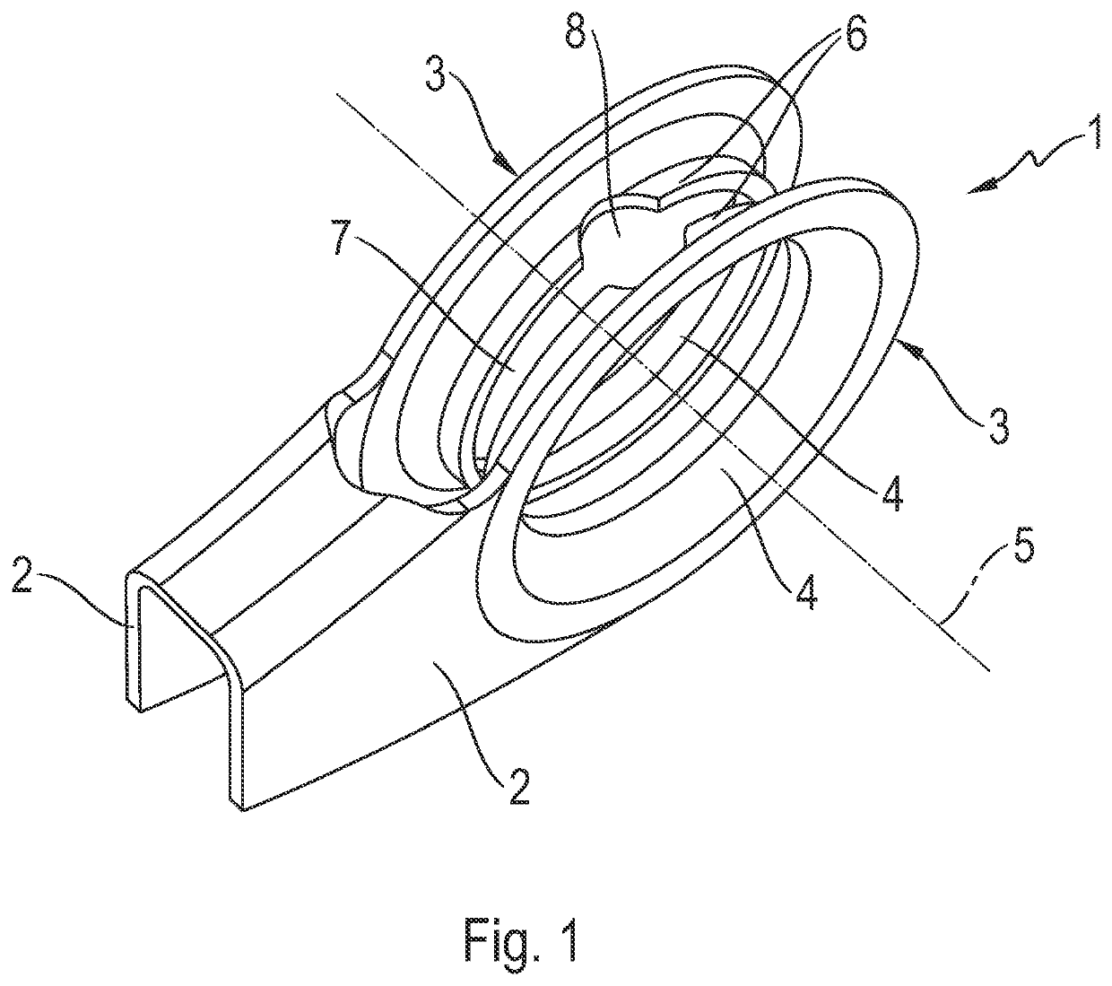
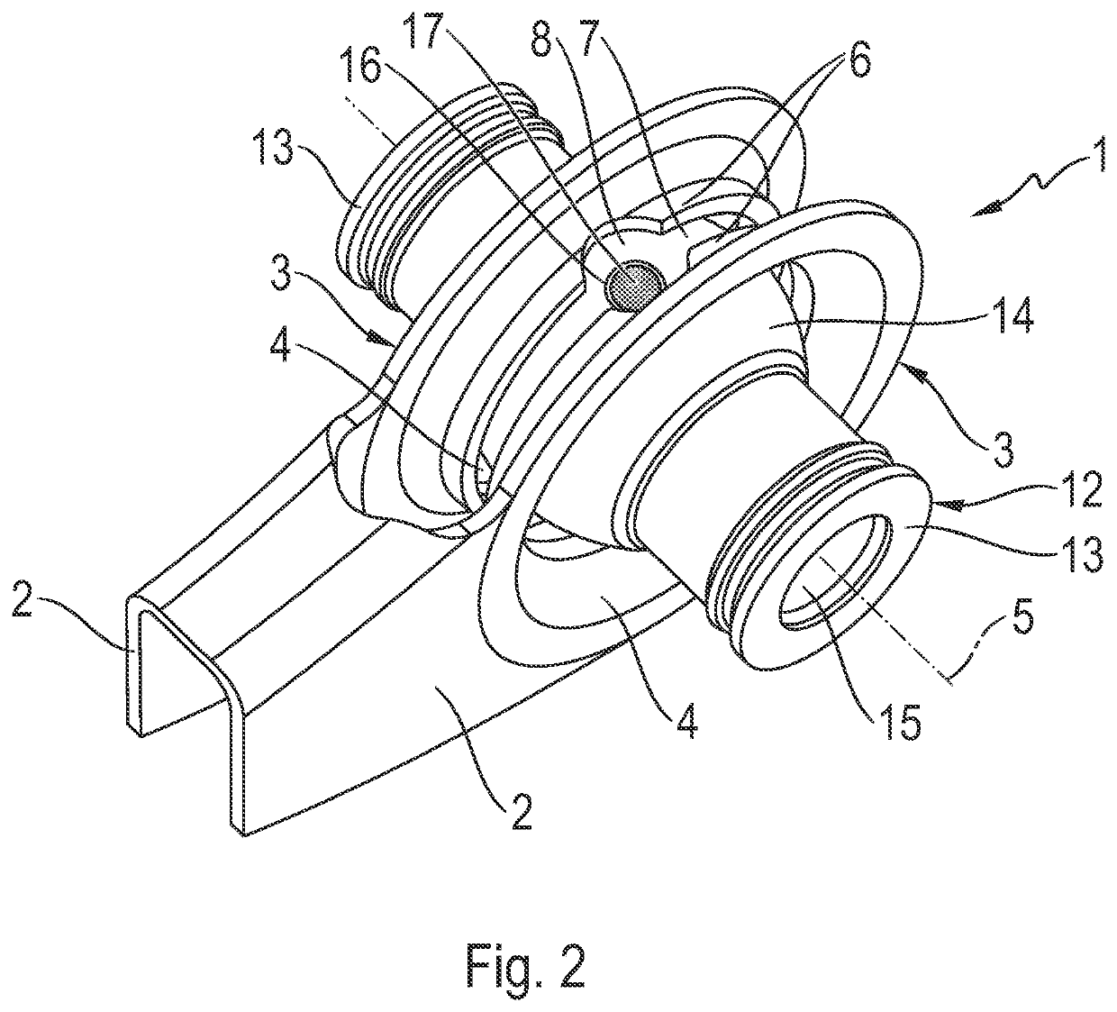
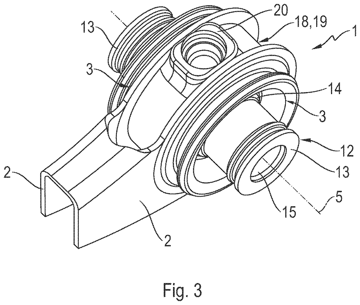
[0033]FIG. 1 shows a partial perspective view of a control arm 1 for a wheel suspension. The control arm 1 is preferably a metallic stamped and bent component, in particular made of steel. The control arm 1 in the form of a stamped and bent component has a U-shaped cross-section with two wall sections 2 extending parallel to one another. At least at one end of the control arm 1 the wall sections 2 are made as receiving sections 3. The receiving sections 3 are connected to the U-shaped wall sections 2 and are essentially of circular shape. The receiving sections 3 each have an eyelet 4, which is arranged coaxially with an axis of symmetry 5 of the receiving sections 3. On the inner side of the respective receiving section 3, there is in each case a section 6 that extends in the axial direction. The two sections 6 are separated a distance apart from one another by an annular gap 7. Viewed in the circumferential direction, the annular gap 7 is interrupted at one point by a circular cut...


PUM


Abstract

A joint (10) with first and second joint components (12, 26; 19) are movably connected to one another. The first joint component (12, 26) has a spherical joint body (14, 28) and the second joint component (19) rotatably and pivotably holds the joint body (14, 28). A sensor device, for determining the position of the first and second joint components (12, 26; 19) relative to one another, is arranged on the joint (10). The sensor device has at least one sensor element (21, 31) which can be integrated in a housing (18) that is produced by an assembly overmolding process. The joint housing (18) forms the second joint component (19) in which the joint body (14, 28) is directly supported.

Description

[0001]This application is a National Stage completion of PCT / EP2019 / 074797 filed Sep. 17, 2019, which claims priority from German patent application serial no. 10 2018 217 643.4 filed Oct. 15, 2018.FIELD OF THE INVENTION[0002]The invention relates to a joint with two joint components movably connected to one another, namely a first joint component comprising a spherical joint body and a second joint component that receives the joint body rotatably and pivotably, wherein a sensor device is arranged on the joint for determining the position of the two joint components relative to one another.[0003]In addition the invention relates to a control arm for a wheel suspension of a motor vehicle. Finally, an object of the invention is a method for assembling a joint onto a control arm of a wheel suspension, wherein the joint comprises two joint components, a first joint component comprising a spherical joint body which is connected to a second joint component that receives the joint body rot...

Claims


Application Information

Patent Timeline
IPC IPC(8): F16C11/06B60G7/00G01D5/16
CPCF16C11/0614B60G7/001B60G7/005B60G2401/17B60G2204/116B60G2204/416B60G2206/81012G01D5/16B60G2204/14B60G2206/16F16C11/0685F16C11/0695F16C2326/05F16C2233/00B60G2204/422
Inventor BRONSWICK, PHILIPPSIEVE, MANFREDPABST, JAN
Owner ZF FRIEDRICHSHAFEN AG
Learn More