
Pull-out type rapid control electric cabinet device

A rapid control and pull-out technology, applied in pull-out switchgear, substation/distribution device housing, switchgear, etc., can solve the problems of complex control part of non-standard equipment, cumbersome installation process, and long laying distance of lines , to achieve the effect of convenient strong current control and air source control, convenient later maintenance, and reducing interference and attenuation

Pending Publication Date: 2021-11-23
GREE ELECTRIC APPLIANCES WUHAN +1
View PDF0 Cites 0 Cited by
  • Summary
  • Abstract
  • Description
  • Claims
  • Application Information

AI Technical Summary

Problems solved by technology

[0003] With the rapid development of non-standard automation applications, the control part of non-standard equipment is becoming more and more complicated. The electric cabinet is attached to the outside of the equipment as an external type, resulting in a long laying distance of the line, and a separate external electric cabinet is required, resulting in cumbersome installation process.

Method used


Image

  • Pull-out type rapid control electric cabinet device
  • Pull-out type rapid control electric cabinet device
  • Pull-out type rapid control electric cabinet device

Examples


Embodiment example 1

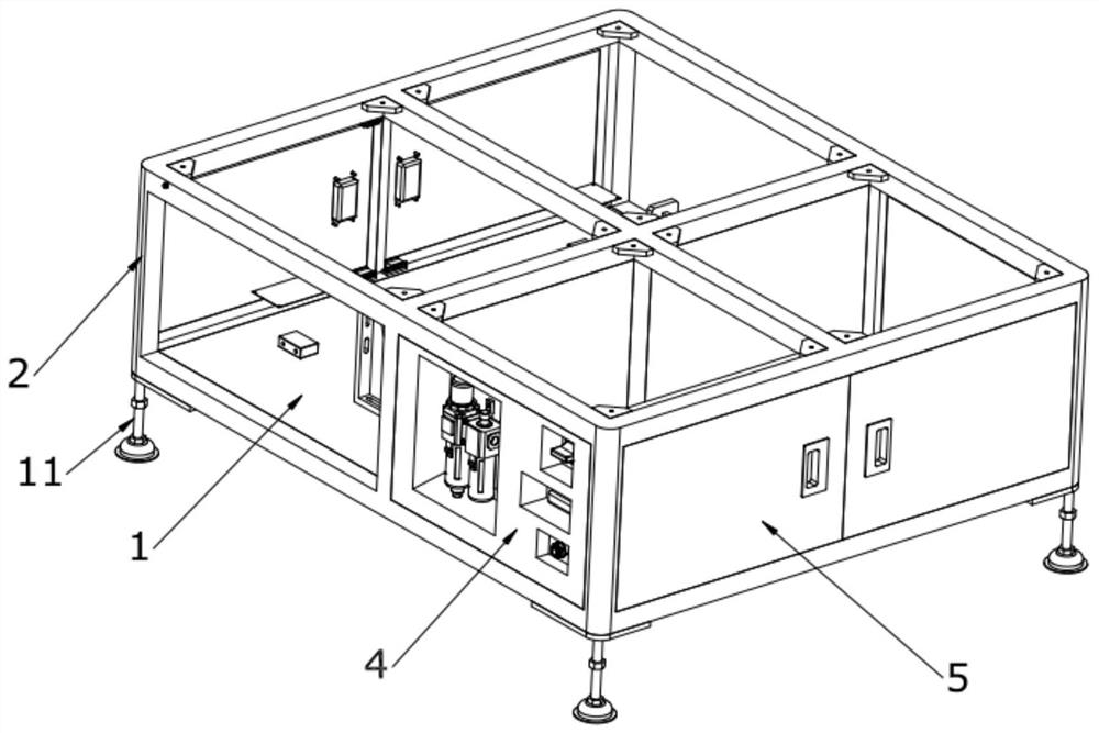
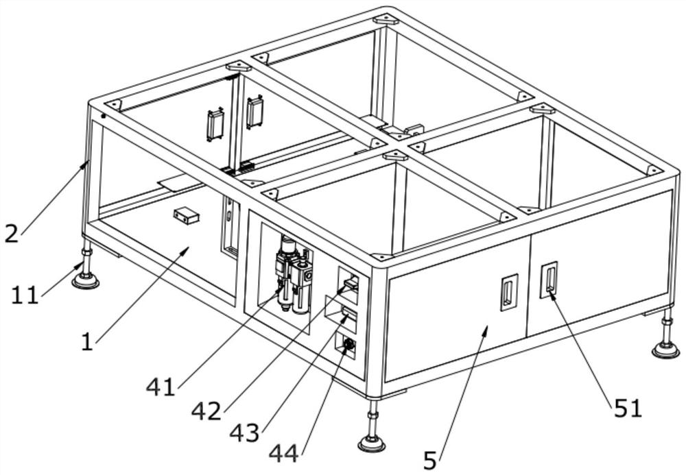
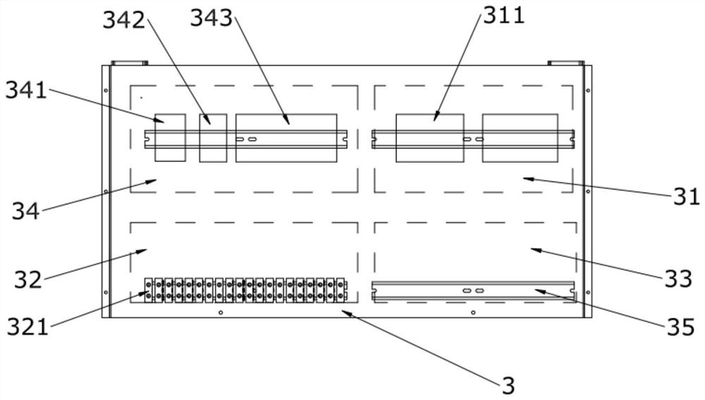
[0047] A pull-type fast control electric cabinet device, including a base, a support frame and an electric control floor, the support frame is fixedly connected to the base, the support frame is a frame structure, and support feet are installed at the bottom of the base, The electric control base plate is used for accommodating the control circuit, and the base is provided with slide rails, and the electric control base plate is slidably connected with the base through the slide rails. The electric control baseboard is provided with a strong current area and a weak current area, the weak current area is provided with connecting terminals, and the strong current area is provided with a servo driver. The electric control base plate is provided with a control area, and the control area is provided with a protection circuit and a PLC controller. The protection circuit is provided with an air switch and a fuse. By providing an air switch and a fuse, electrical safety accidents cau...

Embodiment example 2

[0049] The control electric cabinet device is a horizontal control electric cabinet device, the support frame includes three groups, each group of support frames includes three support rods, and the three groups of support frames are relatively arranged on the base. A support beam is connected above the support bar, and the support beams are vertical in pairs. The support bar and the support beam form a frame structure, and an operation platform is installed on the operation support beam. The rest of the structure is as in the implementation case 1.

Embodiment example 3

[0051] The control electric cabinet device is a vertical control electric cabinet device. The rest of the structure is as in the implementation case 1.


PUM


Abstract

The invention discloses a pull-out type rapid control electric cabinet device which can realize the rapid connection and rapid change between devices. When an execution element needs to be added, a control circuit is directly added in an expansion area, and the control circuits can be quickly connected or replaced without the manual installation of a user, so that the operation is simple and convenient. A single control circuit can work independently, and the plurality of control circuits can also be connected quickly. An electric control bottom plate is in sliding connection with a base through the sliding rails, the position of the electric control bottom plate on the base can be rapidly changed, and the user can conveniently adopt an optimal wiring mode. The control circuits are integrated in the control electric cabinet device, so that the distance between a control part and an execution part is minimized, and interference and attenuation caused by long signal distance are reduced. A strong current area, a weak current area, a control area and an expansion area of the electric control bottom plate are separately arranged, so that the later maintenance can be facilitated; meanwhile, the strong current area and the weak current area are separated, so that the signal interference of a magnetic field generated by the strong current on the weak current can be avoided.

Description

technical field [0001] The invention relates to the technical field of power supply equipment, in particular to a pull-type fast control electric cabinet device. Background technique [0002] Non-standard automation equipment refers to a kind of non-standard automation equipment specially customized according to the actual production process requirements of the product. With the continuous increase of factory labor costs, more and more companies are paying attention to the field of factory automation, which has also brought great development opportunities to the non-standard automation industry. [0003] With the rapid development of non-standard automation applications, the control part of non-standard equipment is becoming more and more complicated. The electrical cabinet is attached to the outside of the equipment as an external device, resulting in a long laying distance of the line, and the need for a separate external electrical cabinet, resulting in cumbersome install...

Claims


Application Information

Patent Timeline
Patent Type & Authority Applications(China)
IPC IPC(8): H02B11/127H02B1/01H02B1/50H02B1/36H02B1/20H02B1/30H02B1/32
CPCH02B11/127H02B1/013H02B1/011H02B1/50H02B1/36H02B1/20H02B1/30H02B1/32
Inventor 张广胡家泉贾玉龙刘爽王向红
Owner GREE ELECTRIC APPLIANCES WUHAN
Learn More