Electronic device comprising elastic connection pins

a technology of elastic connection pins and electrical devices, which is applied in the direction of coupling contact members, coupling device connections, electrical devices, etc., can solve the problems of limited stub effect, and achieve the effect of reliable connection

Active Publication Date: 2021-08-26
SAFRAN ELECTRONICS & DEFENSE
View PDF0 Cites 2 Cited by
  • Summary
  • Abstract
  • Description
  • Claims
  • Application Information

AI Technical Summary

Benefits of technology

[0010]An object of the invention is to provide an el...

Problems solved by technology

In the high-frequency electron...

Method used


Image

  • Electronic device comprising elastic connection pins
  • Electronic device comprising elastic connection pins

Examples


Embodiment Construction

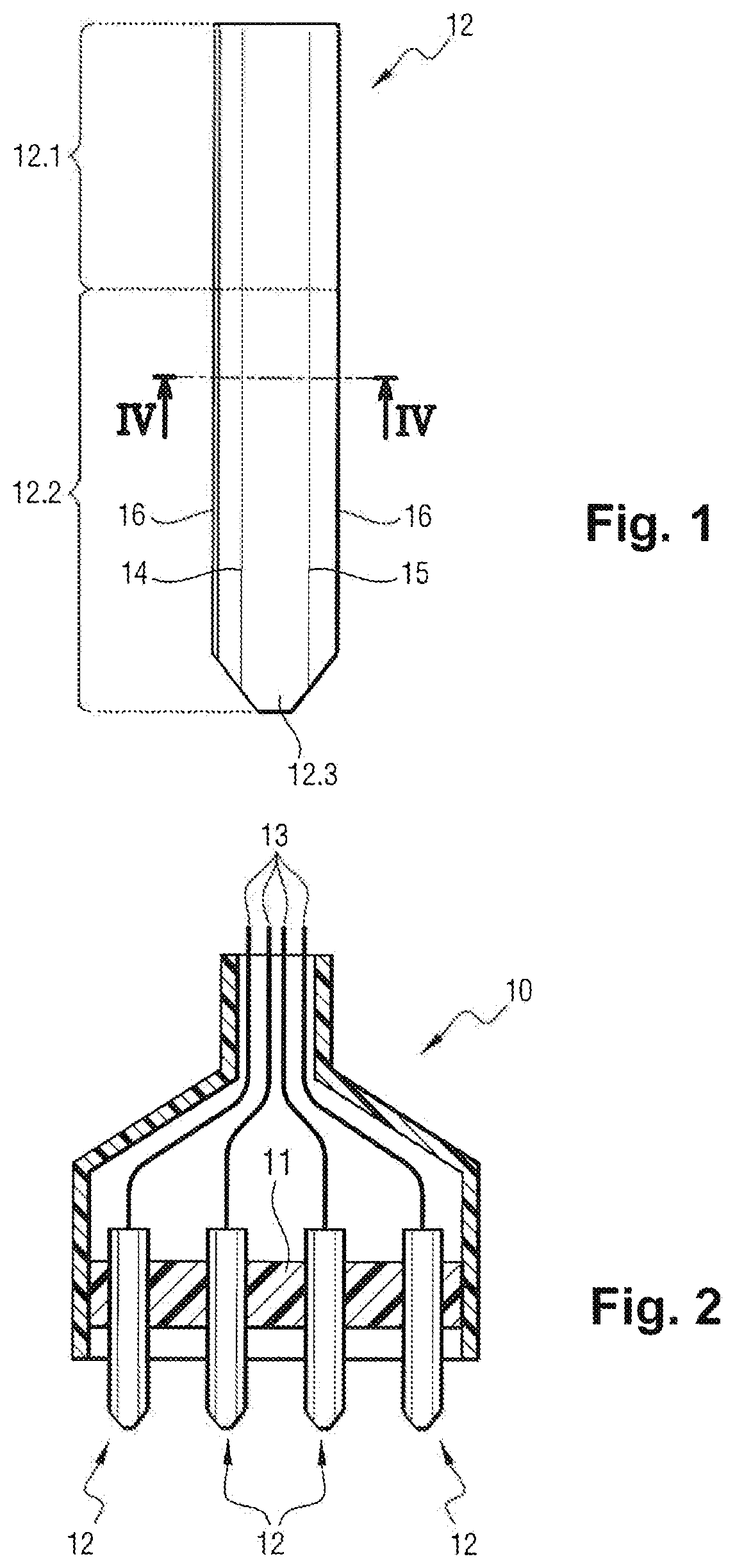
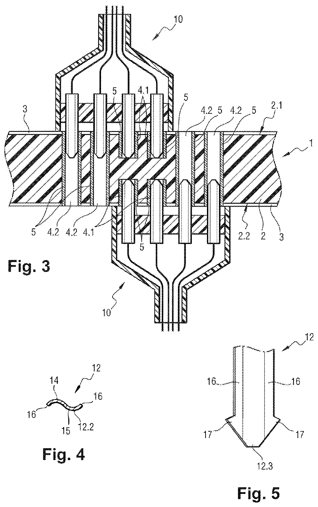
[0029]With reference to FIGS. 1 to 4, the invention is described by way of example in application to an electronic device including a printed circuit board (PCB) given overall reference 1, which PCB comprises an electrically insulating substrate 2 that carries electrically conductive tracks 3 and that is provided with holes 4.1, 4.2, each of which is covered by an internal coating 5 that is connected to an electrically conductive track 3. The conductive tracks 3 are connected to high-frequency electronic components (not shown) and they form a high-frequency circuit.

[0030]The holes include a first series of blind holes 4.1 and a second series of blind holes 4.1 that extend facing each other from opposite faces 2.1 and 2.2 of the substrate 2. The blind holes 4.1 of each facing pair of holes lie on the same axis, and their ends are spaced apart by a distance of about 0.4 mm. Each of the blind holes 4.1 connects together two conductive tracks forming a differential line.

[0031]The holes ...


PUM


Abstract

An electrical connector pin comprising a link segment for linking to the connector and an end segment that is free, the end segment having a cross-section that presents at least one curved portion curved about an axis parallel to a longitudinal direction of the end segment and the end segment having side edges forming electrical contact portions that can be moved towards each other causing the curved portion to deform elastically.

Description

[0001]The present invention relates to the field of electronics, and more particularly to the field of making electrical connections in electronic devices.TECHNOLOGICAL BACKGROUND[0002]It is known that an electronic device or component can be connected to a printed circuit board (PCB) by using a connector having pins for engaging in holes that have been provided in the printed circuit board and that possess inside surfaces covered in an electrically conductive coating and connected to conductor tracks of the printed circuit. These are referred to as plated holes or vias.[0003]A pin is generally made of conductive metal and includes an end segment that is elastically deformable in a direction that is transverse relative to a longitudinal direction of the pin so that the end segment has two outside surface portions that are diametrically opposite each other and suitable for being moved elastically towards each other. The end segment can thus be engaged by force in the plated hole and ...

Claims


Application Information

Patent Timeline
IPC IPC(8): H01R12/71H01R13/6473H01R12/75H01R13/03
CPCH01R12/712H01R13/03H01R12/75H01R13/6473H01R12/585
Inventor GUILLOT, FRANÇOISSPOOR, PASCALROCHE
Owner SAFRAN ELECTRONICS & DEFENSE
Why Eureka
Try Eureka