Medical Device for Anastomosis

a medical device and anastomosis technology, applied in the field of medical devices, can solve the problems of heel buckling/ovalization/kinking, heel flattening, and/or heel buckling/ovalization/kinking, and achieve the effect of sufficient kink resistan

Active Publication Date: 2021-09-02
XELTIS AG
View PDF7 Cites 0 Cited by
  • Summary
  • Abstract
  • Description
  • Claims
  • Application Information

AI Technical Summary

Benefits of technology

[0025]An array of independent rings has sufficient kink resistance for numerous applications of anastomoses in bypassing small diameter vessels.

Problems solved by technology

If a pure polymer tube is sewn at the proximal anastomosis there is the concern of toe flattening, and / or heel buckling / ovalization / kinking.
If an incorporated support element (e.g. a Strain Relief System (SRS)) is used as part of the anastomosis the support element has to be trimmed and this leads to “toe flattening” creating a compromised flow pattern at the inlet.
Additionally, metallic struts that are being incorporated in the anastomosis potentially create a risk of irritation by sharp edges, or migration of fragments, which could result in side effects such as inflammatory response or intimal hyperplasia.

Method used


Image

  • Medical Device for Anastomosis
  • Medical Device for Anastomosis
  • Medical Device for Anastomosis

Examples


Embodiment Construction

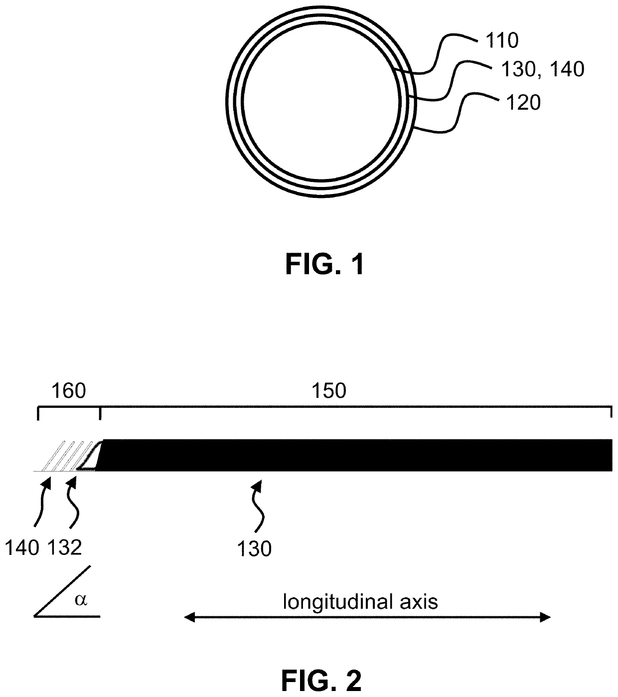
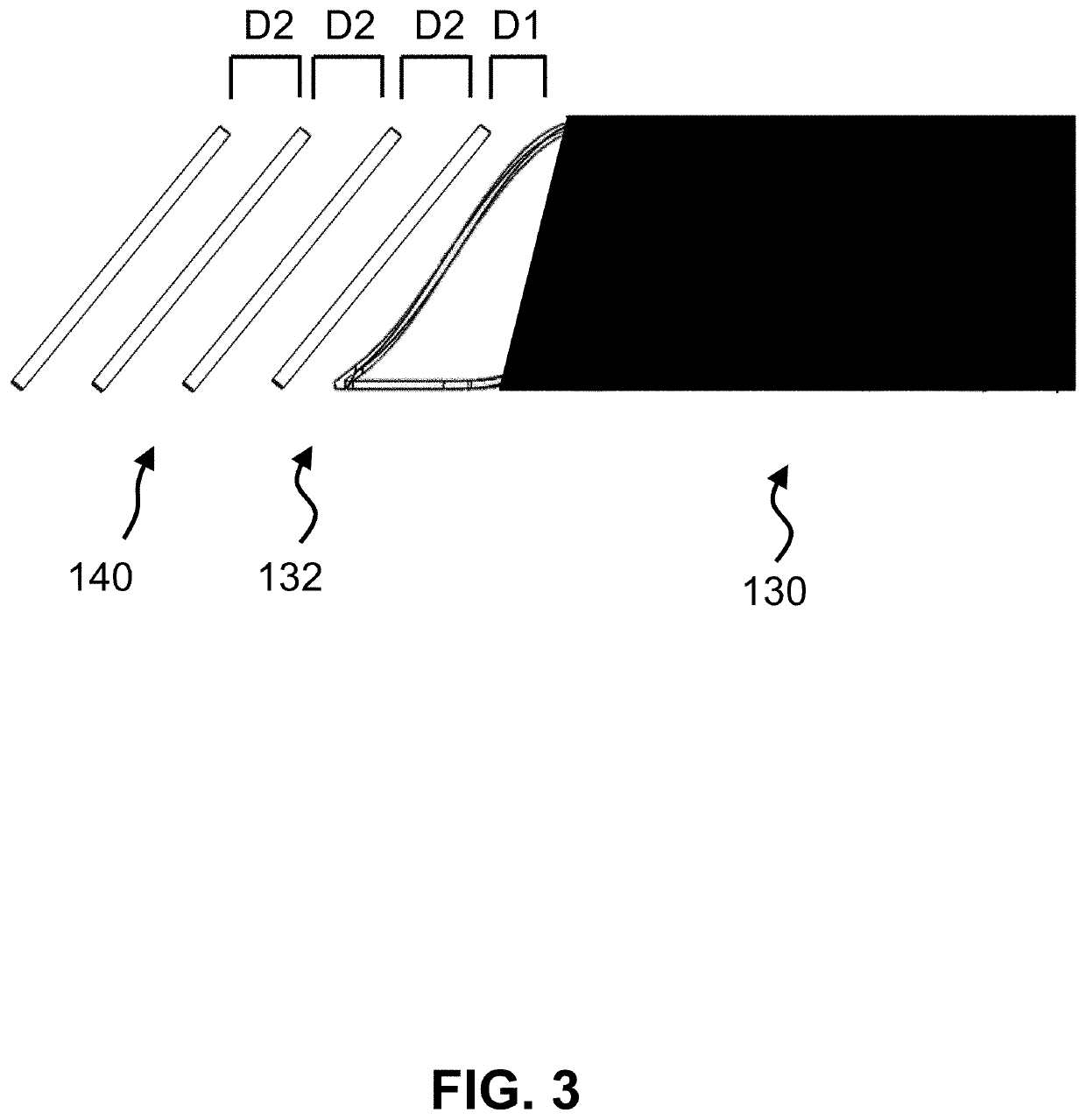
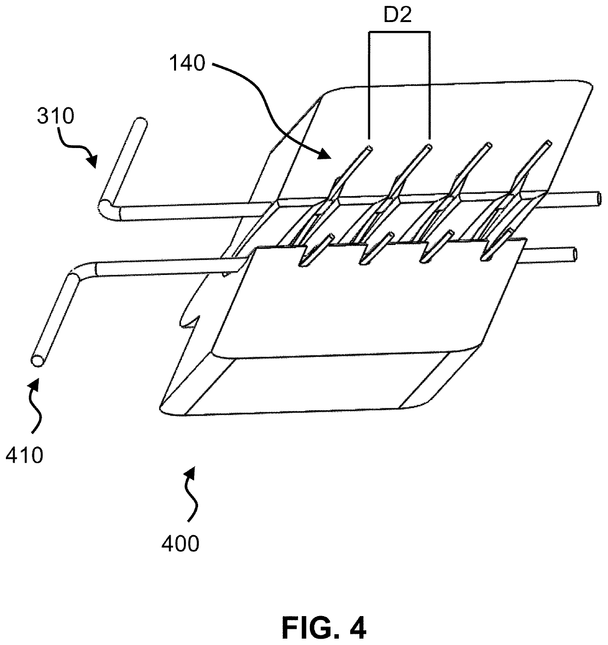
[0030]The present invention is a medical device incorporating a support element for the purposes of anastomosis. Examples of such a support element are a stent, an SRS, a coil, a wire, braid or any other type of support structure typically used in cardiovascular implants. The medical device has two tubular layers (inner layer 110, outer layer 120) that embed the support element 130 as well as two or more independent (separate) C-rings 140 near the end of the support element. A C-ring is defined as either a circular or oval ring that is not fully closed; i.e. has an opening, large enough to accommodate standard surgical scissors for axial slit creation without cutting through the ring strut. In one embodiment, the openings of the C-rings of the two or more independent C-rings are aligned with each other (see FIGS. 2-5). In an alternate embodiment, the C-rings could be closed rings.

[0031]Defining a longitudinal axis of the medical device, the medical device then distinguishes a (main)...


PUM


Abstract

A medical device for an anastomosis is provided. The medical device distinguishes an inner tubular layer, an outer tubular layer, and a support element defining a longitudinal axis. It further distinguishes two or more independent C-rings distributed and positioned at an acute orientation angle relative to the longitudinal axis of the support element at one end of the support element. The support element and the two or more C-rings are embedded in between the inner and the outer tubular layers. The types of applications one could envision are e.g. a proximal anastomosis, distal anastomosis, or side-to-side anastomoses, in a customized pre-fabricated graft. Embodiments of the invention could also be incorporated into an anastomotic connector device design. Embodiments of the invention could further be envisioned as vascular grafts applications such as Coronary Artery Bypass Graft (CABG), dialysis access grafts and peripheral vascular applications.

Description

CROSS-REFERENCE TO RELATED APPLICATIONS[0001]This application claims priority from U.S. Provisional Patent Application 62 / 982,161 filed Feb. 27, 2020, which is incorporated herein by reference.FIELD OF THE INVENTION[0002]This invention relates to medical devices. In particular, the invention relates to a medical device for anastomosisBACKGROUND OF THE INVENTION[0003]Coronary artery bypass graft (CABG) surgery is a surgical procedure to restore blood flow to an obstructed coronary artery. When considering a CABG proximal anastomosis, the proximal portion of the graft is required to be trimmed at nominally about a 45 degree-angle and sutured to a punched hole in the aorta. If a pure polymer tube is sewn at the proximal anastomosis there is the concern of toe flattening, and / or heel buckling / ovalization / kinking. If an incorporated support element (e.g. a Strain Relief System (SRS)) is used as part of the anastomosis the support element has to be trimmed and this leads to “toe flattenin...

Claims


Application Information

Patent Timeline
Patent Type & Authority Applications(United States)
IPC IPC(8): A61B17/11
CPCA61B17/11A61B2017/1107A61B2017/1132A61B2017/00526A61B2017/1135A61F2/064A61F2002/072A61F2210/0076
Inventor GRAY, YONATANEL-KURDI, MOHAMMED
Owner XELTIS AG
Why Eureka
Try Eureka