
Electrospun polymer assemblies for medical implant applications

a technology of electrolyte and polymer, applied in the field of tissue engineering products and methods, can solve the problems of no growth possibility, coagulation, degeneration, and current cardiovascular substitutes encounter risks, and achieve the effects of improving hemostasis (bleeding), improving kink resistance, and improving kink resistan

Pending Publication Date: 2022-02-17
XELTIS AG
View PDF0 Cites 1 Cited by
  • Summary
  • Abstract
  • Description
  • Claims
  • Application Information

AI Technical Summary

Benefits of technology

The invention relates to a method of assembling electrospun components, such as heart valves or vascular grafts, using ultrasonic welding. The method avoids the use of sutures, which can cause stress concentration and manual processing, while keeping the potential for tissue ingrowth. The patterned weld also improves kink resistance, which ensures sufficient strength for the implant. The invention provides more precise, reproducible, and automated assembly of electrospun components, and avoids the need for extra materials. Overall, the invention improves the mechanical properties and hemostasis of the implant.

Problems solved by technology

Currently used cardiovascular substitutes encounter risks due to coagulation, infections, degeneration, and no growth possibilities.
When considering bioabsorbable polymeric scaffolds as leaflet material, common methods are not always applicable and stitching techniques demonstrate compromised durability due to tearing especially in areas of higher stress where the stitches are located.
Another aspect to consider as a disadvantage for a use of stitches at the posts would be a possible formation of calcification deposits around the posts in vivo which is caused by stitches and / or laser cut holes for accurate sewing of the stitches.
This observation could potentially lead to degraded valve hemodynamics and in vivo durability.

Method used


Image

  • Electrospun polymer assemblies for medical implant applications
  • Electrospun polymer assemblies for medical implant applications
  • Electrospun polymer assemblies for medical implant applications

Examples


Embodiment Construction

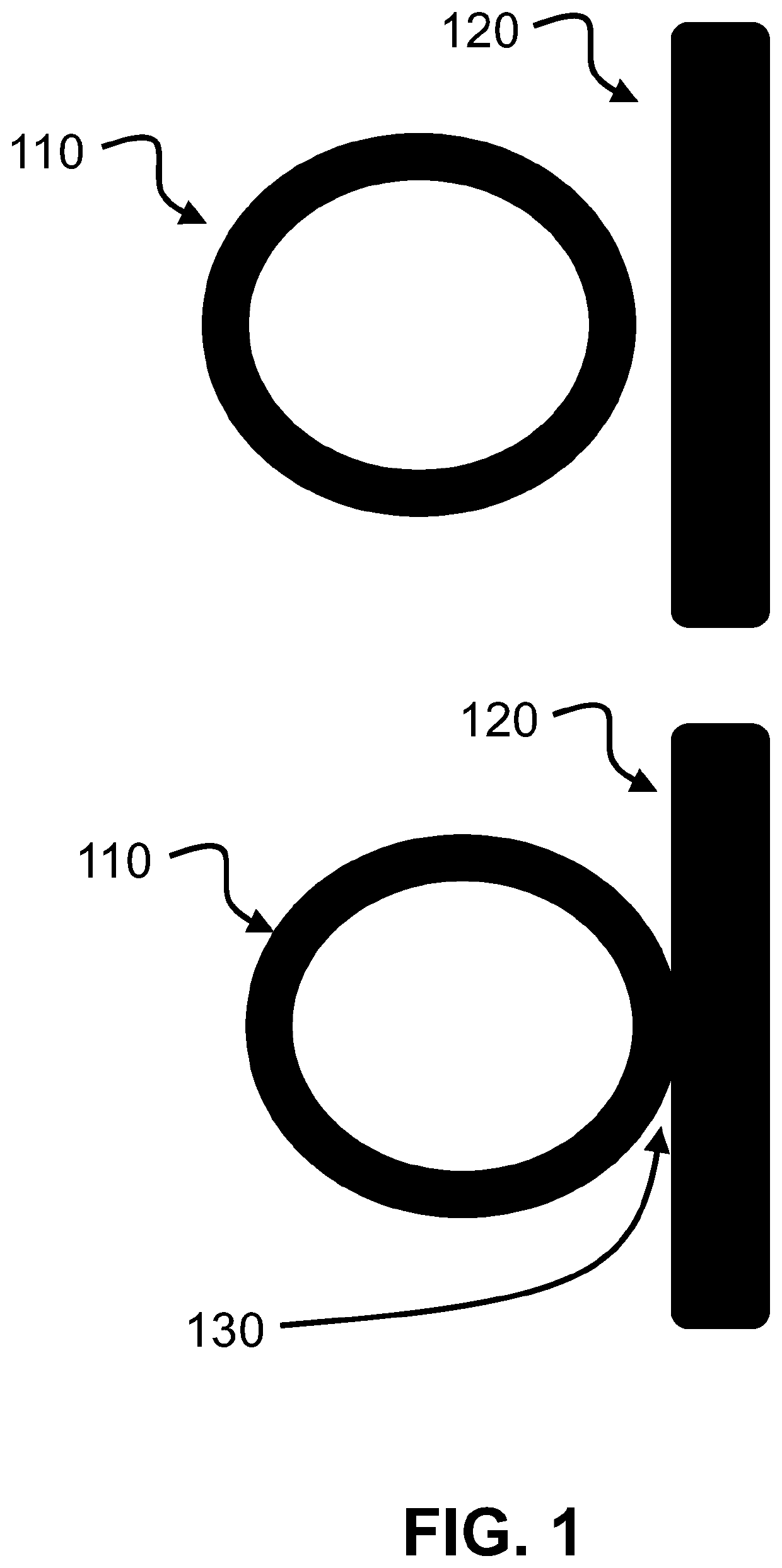
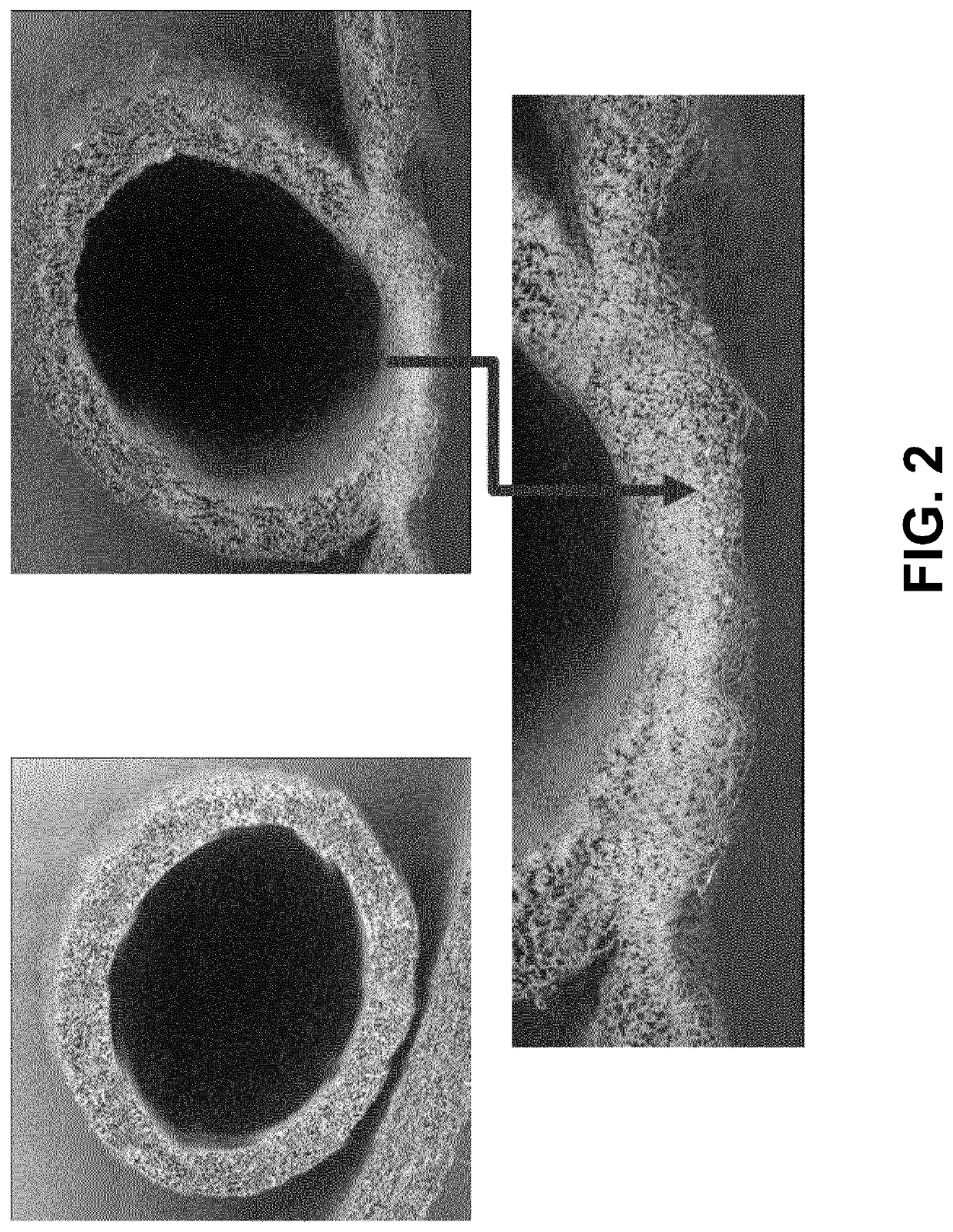
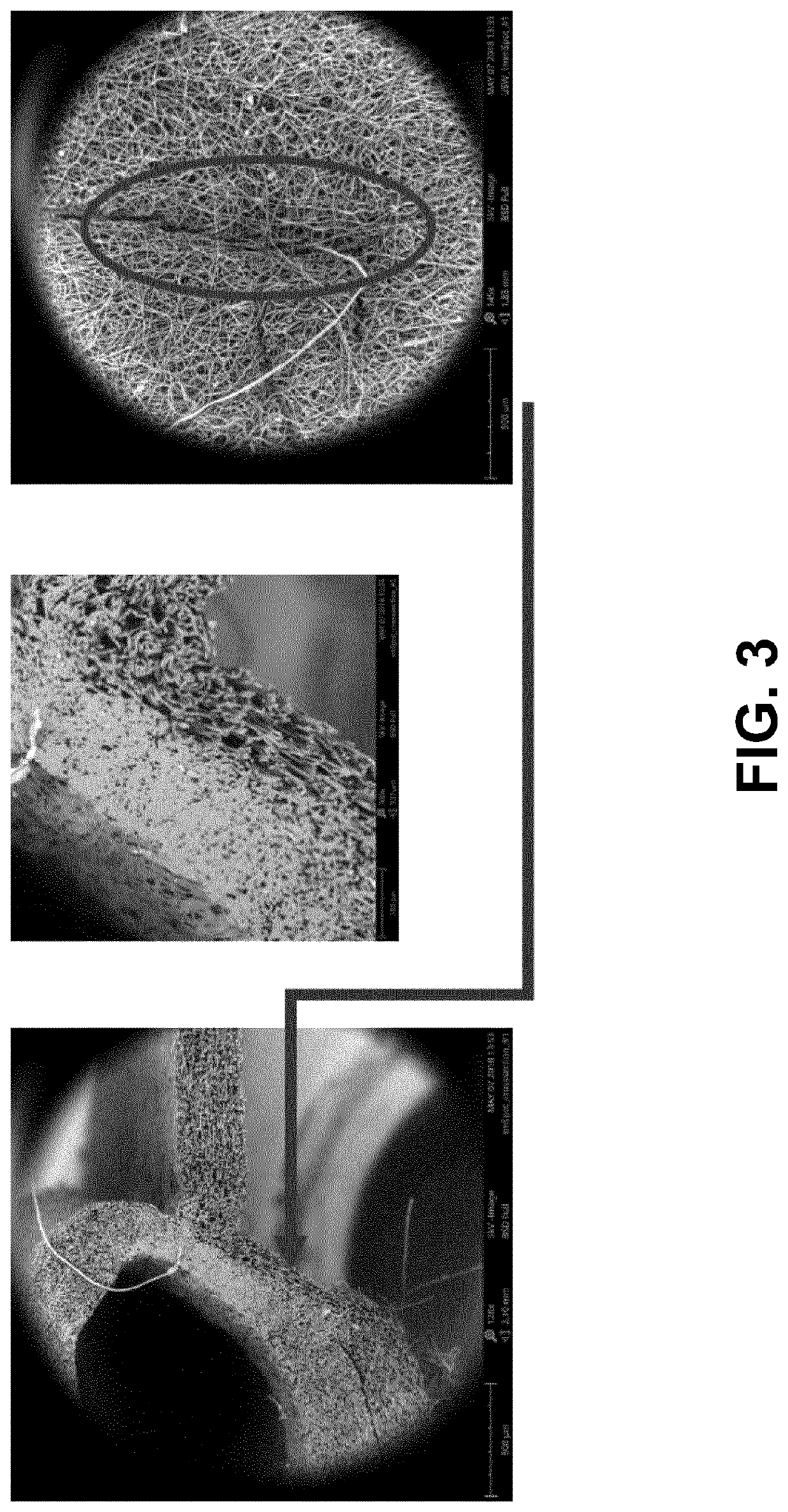
[0027]Embodiments of the invention are medical implants formed by separate components which are made of the same electrospun polymers and whereby the separate components are assembled or joint together using their own polymers or the same type of polymers. Two examples are provided. In the first example, the two separate components are ultrasonically welded together such that the polymers of the two separate components create the assembly or joint. In the second example, the two separate components are glued together with the same polymers as used for the separate polymers. In other words, the medical implant is composed of two separately created components which are assembled or joint together using the same polymers as used for the creation of the components. This results in an implant having the same polymers yet individually created. An example of such implant is heart valve with one or more leaflet components and possibly one or more support structures which is then assembled w...


PUM

PropertyMeasurementUnit
frequencyaaaaaaaaaa
frequencyaaaaaaaaaa
timeaaaaaaaaaa

Abstract

A medical implant is provided that has a first and a second electrospun component with the same type of biodegradable electrospun polymers. In one example, the second electrospun component is separately manufactured from the first electrospun component. Furthermore, the implant is structured such that the first electrospun component and the second electrospun component are assembled or joint together by the same type biodegradable electrospun polymers as in the first electrospun component and the second electrospun component. The assembled implant is a porous, biodegradable medical implant capable of being replaced by naturally ingrown tissue over time upon implantation. Advantages are the avoidance of sutures and the problems associated with the use of sutures, capability of ETR, avoidance of the need for extra materials, allowance for more precise and reproducible assembled structures for which the process could be automated.

Description

FIELD OF THE INVENTION[0001]This invention relates to tissue engineering products and methods.BACKGROUND OF THE INVENTION[0002]Cardiovascular diseases are one of the biggest causes of deaths worldwide. One way to treat at least some of these diseases is by tissue engineering. Tissue engineering can be used for the replacement of cardiovascular tissues, such as arteries and heart valves. Most commonly used heart valve replacements today are bioprosthetic heart valves, which typically contain mainly animal-derived tissue as leaflet material. The tissue of the leaflets is normally sewn together and connected to the valve by stitching. Moreover, the animal tissue is going through chemical fixation to allow specific shape set for optimal hemodynamics without compromising material properties and leaflet durability.[0003]Currently used cardiovascular substitutes encounter risks due to coagulation, infections, degeneration, and no growth possibilities. Tissue engineering is based on endogen...

Claims


Application Information

Patent Timeline
Patent Type & Authority Applications(United States)
IPC IPC(8): A61F2/24
CPCA61F2/2418A61F2240/001A61F2220/005A61F2220/0058A61L27/14A61L27/56A61L27/58A61L31/04A61L31/146A61L31/148A61L2400/12A61L2430/20
Inventor GRAY, YONATANCOX, MARTIJN ANTONIUS JOHANNES
Owner XELTIS AG
Learn More