Method for producing a ductwork damper, ductwork damper, and ductwork damper unit incorporating same

a technology of ductwork damper and ductwork, which is applied in the direction of mechanical equipment, lighting and heating apparatus, heating types, etc., can solve the problems of complex production and numerous components of ductwork dampers, and achieve the effects of improving properties, reducing costs, and non-reactiveness

Pending Publication Date: 2021-09-02
CAPITAL HARDWARE SUPPLY LLC
View PDF0 Cites 0 Cited by
  • Summary
  • Abstract
  • Description
  • Claims
  • Application Information

AI Technical Summary

Benefits of technology

[0021]Improved ductwork is also disclosed for directing conditioned air in a predetermined direction, which comprises a damper according to the present invention rotatably mounted in the ductwork on bushings constructed according to the present invention, whereby loss of conditioned air between the pivot arms of the damper and the bushing is eliminated due to the unique bushings on which the damper is pivotally mounted.
[0022]As noted, the bushing of the present invention is preferably made of a soft pliable flexible and resilient material, such as natural or synthetic rubber. Silicone rubber is preferred, due particularly to its physical characteristics, as well as its capability to be formed and dimensioned within predetermined units. Silicone rubber is a rubber-like material composed of silicone itself a polymer-c

Problems solved by technology

Known air duct dampers have numerous comp

Method used


Image

  • Method for producing a ductwork damper, ductwork damper, and ductwork damper unit incorporating same
  • Method for producing a ductwork damper, ductwork damper, and ductwork damper unit incorporating same
  • Method for producing a ductwork damper, ductwork damper, and ductwork damper unit incorporating same

Examples


Embodiment Construction

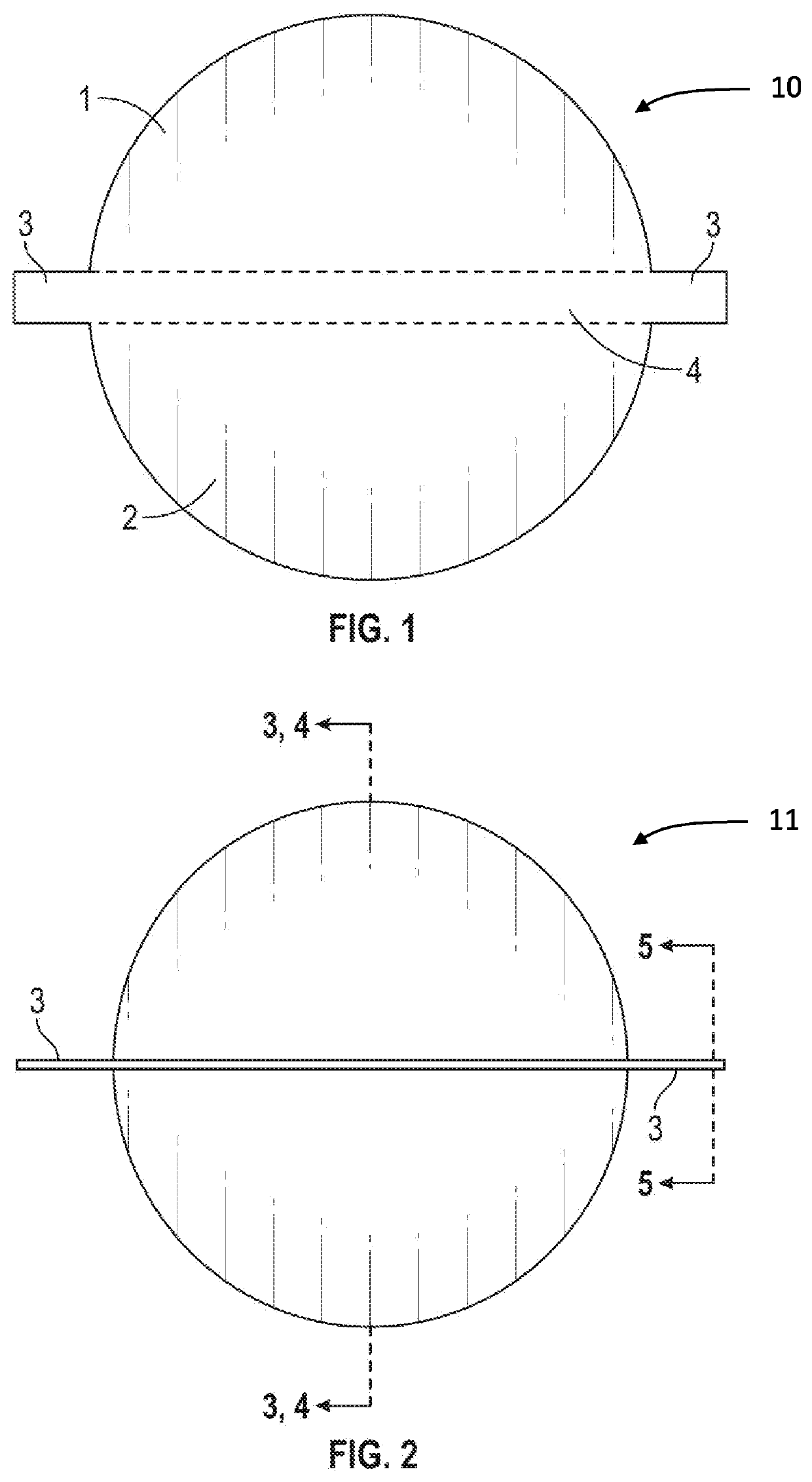
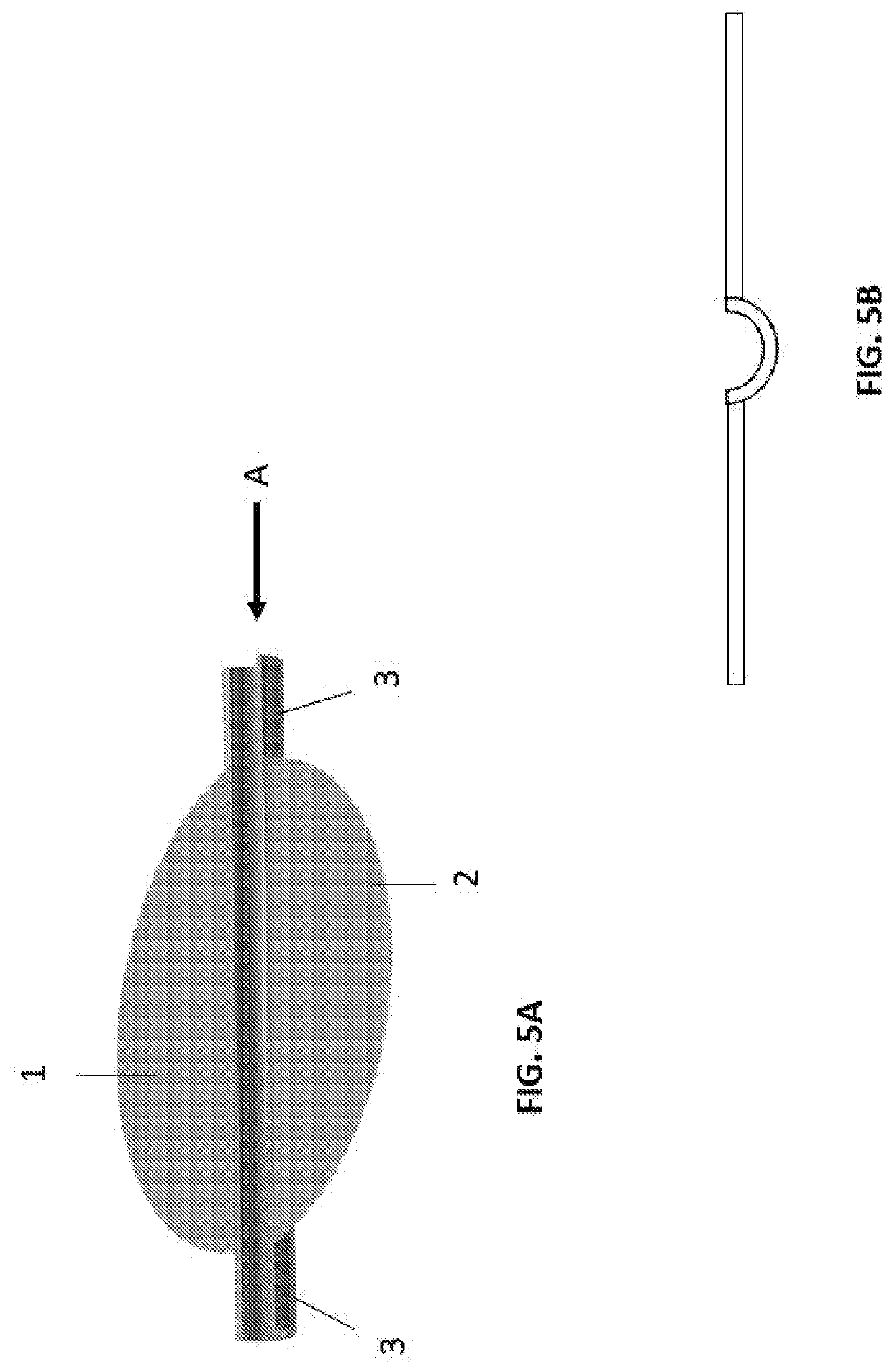
[0039]FIGS. 1 and 2 schematically illustrate the steps of an embodiment of the process for producing a damper 11 according to the present invention. FIG. 1 shows a preform 10 of the damper 11 that was stamped from sheet metal stock. The preform 10 has a body 20 and two diametrically opposed arms 3 extending radially from the body 20 from opposite sides of the body 20. In the embodiment shown in FIG. 1, the body 20 comprises two substantially semi-circular portions 1, 2 and a central portion 4 between the two substantially semicircular portions 1, 2.

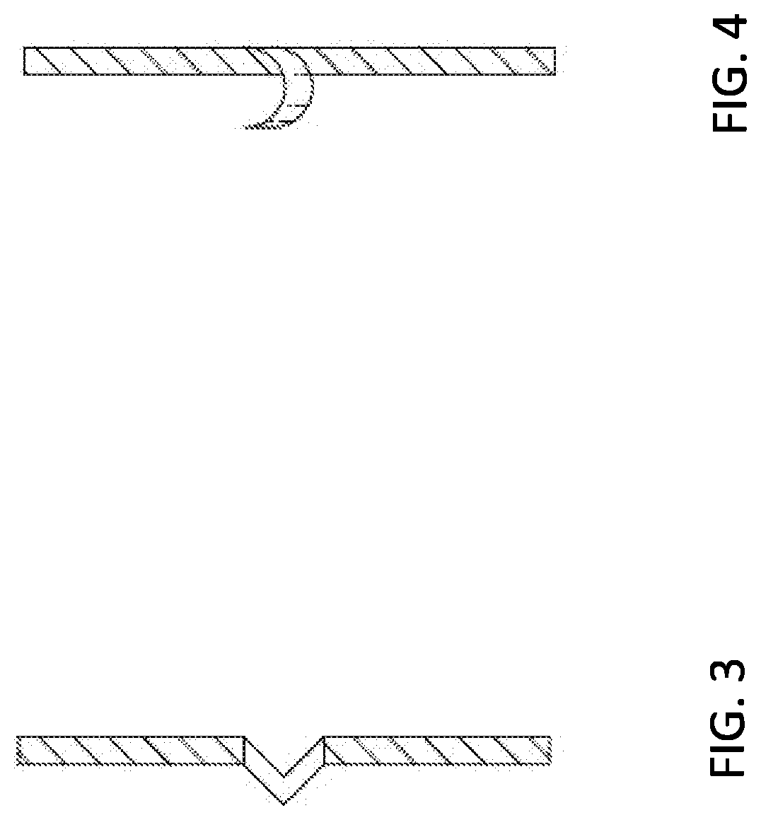
[0040]The preform 10 produced in the stamping step is subjected to a forming step in which an indentation is formed in the preform 10 that extends substantially centrally along the central portion 4 from the end 3a of one of the arms to the end 3b of the other arm. As a result of the indentation, the two substantially semicircular portions 1, 2 are positioned closer to each other and together define a substantially circular shape.

[0041]Th...


PUM


Abstract

A method for producing an air duct damper includes the steps of punching from sheet metal stock a damper preform having a body and two diametrically opposed arms extending from opposite sides of the body; and forming an indentation in the damper preform extending between and up to respective ends of the two arms.

Description

CROSS-REFERENCE TO RELATED APPLICATIONS[0001]This application claims priority to U.S. provisional application No. 62 / 850,020, filed May 20, 2019, the disclosure of which is incorporated in its entirety by reference herein, and made a part of this application.FIELD OF THE INVENTION[0002]The present invention relates to improved dampers for pivotal mounting in cooling and heating ductwork.BACKGROUND OF THE INVENTION[0003]Conventional heating, ventilating and air-conditioning (HVAC) systems utilize vast lengths of sheet metal duct work to convey conditioned air throughout buildings of all types, including residential, industrial, office, medical and apartment buildings. Such HVAC systems include a great many pivotable damper blades situated in air ducts at selected locations to facilitate adjustments at the air flow as required.[0004]In many conventional circular tube HVAC duct systems, each damper is a circular disk pivotably mounted via bearing elements mounted on the side and extend...

Claims


Application Information

Patent Timeline
IPC IPC(8): F24F13/14F16K1/22B21K1/24
CPCF24F13/14B21K1/24F24F13/1406F16K1/22F16K1/222F24F13/1486
Inventor YOSKOWITZ, DAVID
Owner CAPITAL HARDWARE SUPPLY LLC
Why Eureka
Try Eureka