
Imaging device and imaging method

a technology of imaging device and image, which is applied in the direction of optical radiation measurement, instruments, television systems, etc., can solve the problems of large number of specular reflected light components, inability to align the other polarization direction with the direction, and inability to accurately calculate the spectral reflectan

Pending Publication Date: 2021-09-02
FUJIFILM CORP
View PDF0 Cites 0 Cited by
  • Summary
  • Abstract
  • Description
  • Claims
  • Application Information

AI Technical Summary

Benefits of technology

This invention provides an imaging device and method that can prevent differences in appearance between images generated based on light with different polarization directions. The device includes a first polarizer that aligns the polarization direction of the light transmitted through different pupil regions with a first polarization direction. This reduces the difference in appearance caused by the difference in polarization directions between different images. The device also includes a wave plate that converts the linearly polarized light into circularly or elliptically polarized light. This flexibility in the design of the polarization direction of the light forming the obtained images allows for multiple images with uniform light amounts. By aligning the polarization direction of the light transmitted through different pupil regions with the first polarization direction and converting the linearly polarized light into circularly or elliptically polarized light, this invention generates images with uniform light amounts regardless of the polarization direction.

Problems solved by technology

As such, in a case in which images are generated on the basis of light having different polarization directions without aligning the polarization directions even once, the following problems may occur.
However, in a case in which light having different polarization directions is generated from the beginning, one polarization direction can be aligned with a direction in which the s-polarized light is shielded, but it is difficult to align the other polarization direction with the direction in which the s-polarized light is shielded.
However, in a case in which images based on light having different polarization directions are used without aligning the polarization directions even once, the spectral reflectance may not be calculated properly.
Specifically, in the images based on the light having different polarization directions which have been obtained without aligning the polarization directions even once, for a high glossy portion of the object, the number of specular reflected light components is large, and the correct spectral reflectance is not obtained.

Method used


Image

  • Imaging device and imaging method
  • Imaging device and imaging method
  • Imaging device and imaging method

Examples


first embodiment

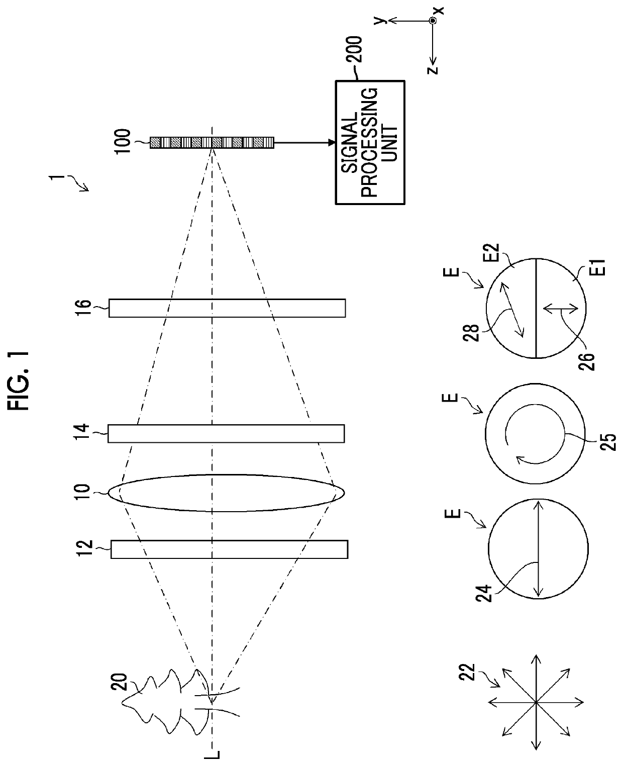
[0054]FIG. 1 is a diagram illustrating a schematic configuration of an imaging device 1 according to a first embodiment. In this embodiment, two independent images are acquired by using two different polarization directions (a second polarization direction 26 and a third polarization direction 28).

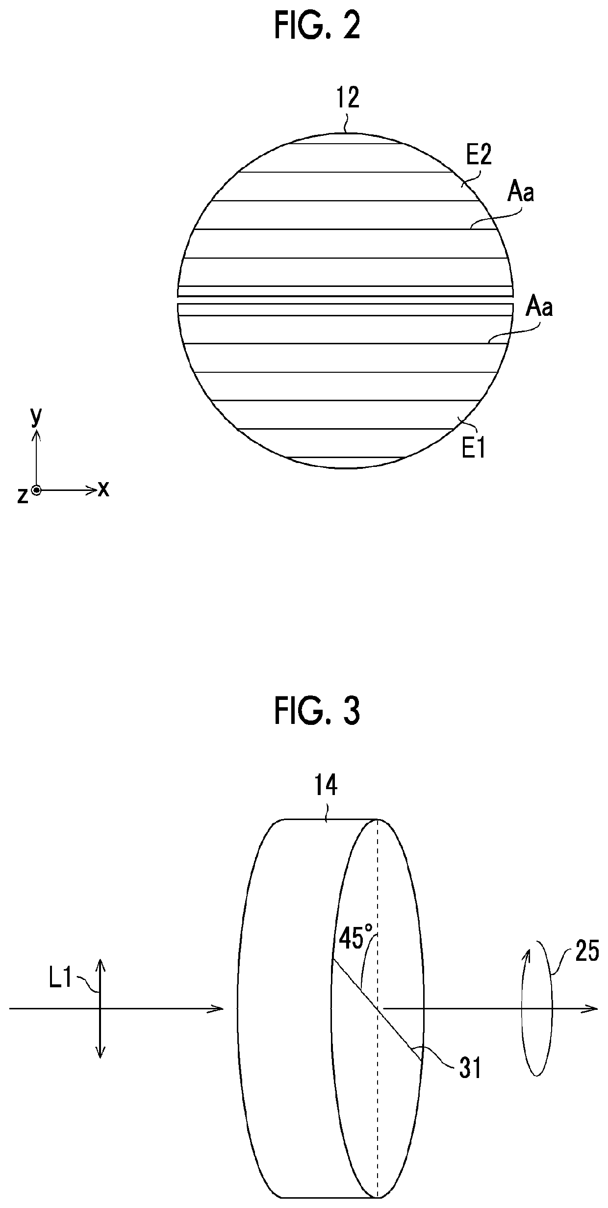
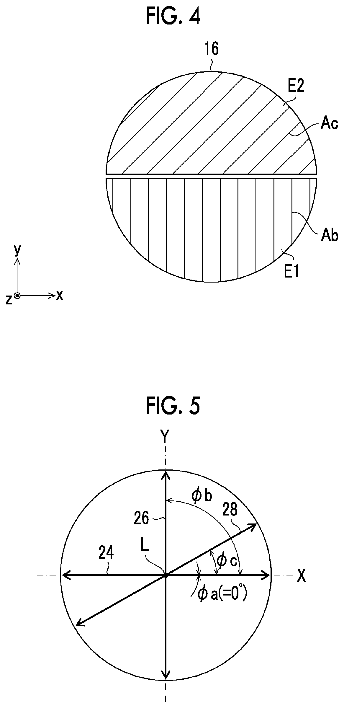
[0055]As illustrated in FIG. 1, the imaging device 1 according to this embodiment comprises an imaging optical system 10, a first polarization filter (first polarizer) 12, a wave plate 14, a second polarization filter (a second polarizer and a third polarizer) 16, an imaging element 100, and a signal processing unit 200. In addition, in FIG. 1, a polarization direction 22 of natural light reflected by an object 20, a first polarization direction 24 which is a polarization direction of light transmitted through the first polarization filter 12, circularly polarized light 25 converted by the wave plate 14, and the second and third polarization directions 26 and 28 which are the polarization ...

second embodiment

[0119]Next, a second embodiment of the invention will be described. In this embodiment, a wavelength filter (bandpass filter) 40 is provided, and it is possible to independently obtain images of each wavelength band.

[0120]FIG. 17 is a diagram illustrating a schematic configuration of an imaging device 1 according to this embodiment. In addition, the portions already described in FIG. 1 are denoted by the same reference numerals, and the description thereof will not be repeated.

[0121]As illustrated in FIG. 17, the imaging device 1 according to this embodiment comprises an imaging optical system 10, a first polarization filter 12, a wave plate 14, the wavelength filter 40, a second polarization filter 16, an imaging element 100, and a signal processing unit 200. Further, the position where the wavelength filter 40 is provided is not limited to between the wave plate 14 and the second polarization filter 16 and is not particularly limited as long as light transmitted through the first ...

third embodiment

[0125]Next, a third embodiment of the invention will be described. In this embodiment, three different polarization directions (a second polarization direction 26, a third polarization direction 28, and a fourth polarization direction 30) are used to independently acquire three images.

[0126]FIG. 19 is a diagram illustrating a schematic configuration of an imaging device 1 according to the third embodiment. In addition, the portions already described in FIGS. 1 and 17 are denoted by the same reference numerals, and the description thereof will not be repeated.

[0127]As illustrated in FIG. 19, the imaging device 1 according to this embodiment comprises an imaging optical system 10, a first polarization filter 12, a wave plate 14, a wavelength filter 40, a second polarization filter 16, an imaging element 100, and a signal processing unit 200. Further, FIG. 19 illustrates a polarization direction 22 of natural light reflected by an object 20, the first polarization direction 24 which is...


PUM


Abstract

Provided are an imaging device and an imaging method that can suppress a difference in appearance caused by a difference between the polarization directions of received light in a case in which different images are generated on the basis of light having different polarization directions, have flexibility in the design of the polarization direction of light forming different images, and can generate a plurality of images having a uniform amount of light. An imaging device (1) includes: an imaging optical system (10); a first polarizer that aligns a polarization direction of light transmitted through a first pupil region (E1) and a second pupil region (E2); a wave plate (14) that converts the light into circularly or elliptically polarized light; a second polarizer that transmits light in a second polarization direction different from the first polarization direction; a third polarizer that transmits light in a third polarization direction different from the first polarization direction and the second polarization direction; an imaging element (100) that has a plurality of pixel units receiving the light transmitted through the first pupil region and the second pupil region; and an image generation unit.

Description

CROSS-REFERENCE TO RELATED APPLICATIONS[0001]The present application is a Continuation of PCT International Application No. PCT / JP2019 / 042861 filed on Oct. 31, 2019 claiming priority under 35 U.S.C § 119(a) to Japanese Patent Application No. 2018-220491 filed on Nov. 26, 2018. Each of the above applications is hereby expressly incorporated by reference, in its entirety, into the present application.BACKGROUND OF THE INVENTION1. Field of the Invention[0002]The present invention relates to an imaging device and an imaging method, and more particularly, to an imaging device and an imaging method that independently acquire a plurality of images with one imaging element.2. Description of the Related Art[0003]In the related art, a technique has been proposed in which light in two different polarization directions is acquired by different pixels to acquire two independent images.[0004]For example, JP2009-169096A discloses a technique in which light in two different polarization directions ...

Claims


Application Information

Patent Timeline
IPC IPC(8): H04N5/217G02B5/30G02B5/20
CPCH04N5/2175G02B5/201G02B5/3025H01L27/14627H01L27/14625G02B3/0056G01J3/0224G02B27/286G01J3/2803H04N23/55H04N25/70H04N23/12H04N25/62
Inventor ONO, SHUJI
Owner FUJIFILM CORP
Learn More