System and method for diagnosing pneumatic control valve online

Active Publication Date: 2021-09-09
KOREA HYDRO & NUCLEAR POWER CO LTD
View PDF0 Cites 0 Cited by
  • Summary
  • Abstract
  • Description
  • Claims
  • Application Information

AI Technical Summary

Benefits of technology

The described method and system can diagnose pneumatic control valves online and in real-time, allowing for efficient diagnosis and prevention of failures. The technique involves obtaining important diagnostic signals and transmitting them to a remote location for analysis and prediction of future progress.

Problems solved by technology

However, a system that is able to diagnose in online in a remote location is still not existed.
Accordingly, there is a problem that separate equipment for diagnosing a valve is moved to the place where the valve is installed and the valve is directly diagnosed, when it is required, and diagnosis is not available while the valve is driven.

Method used


Image

  • System and method for diagnosing pneumatic control valve online
  • System and method for diagnosing pneumatic control valve online
  • System and method for diagnosing pneumatic control valve online

Examples


Embodiment Construction

[0028]The present invention may have various modifications and various embodiments and specific embodiments will be illustrated in the drawings and described in detail in the detailed description.

[0029]However, this does not limit the present invention to specific embodiments, and it should be understood that the present invention covers all the modifications, equivalents and replacements included within the idea and technical scope of the present invention.

[0030]Terms including as first, second, and the like are used for describing various constituent elements, but the constituent elements are not limited by the terms. The terms are used only to discriminate one constituent element from another component. For example, a first component may be referred to as a second component, and similarly, the second component may be referred to as the first component without departing from the scope of the present invention. A term ‘and / or’ includes a combination of a plurality of associated dis...


PUM


Abstract

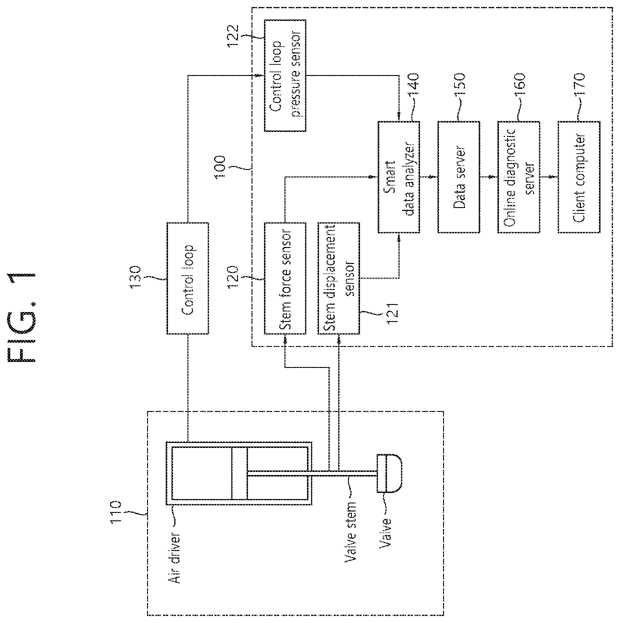
System for diagnosing pneumatic control valve online include a sensor set having sensors, attached to a pneumatic control valve, for measuring the state of the pneumatic control valve, a smart data analyzer for processing sensor signal acquired in real time from the sensor set and generating pneumatic control valve state information for online automatic diagnosis of the pneumatic control valve, a data server for transmitting, to an online analysis server, the pneumatic control valve state information received in real time from the smart data analyzer and storing the pneumatic control valve state information for predetermined time period, the online diagnostic server for, by comparing the pneumatic control valve state information with pre-stored normal state data of the pneumatic control valve, determining whether the pneumatic control valve is in abnormal state and generating diagnostic information, and a client computer for displaying the diagnostic information received from the online diagnostic server.

Description

TECHNICAL FIELD[0001]The present invention relates to a pneumatic control valve and, more particularly, to a method and system for diagnosing a pneumatic control valve.BACKGROUND ART[0002]A pneumatic control valve is a device that performs very important role in power plant operation such as rate of flow adjustment, tank level adjustment, and the like in a power plant, and needs to be driven without failure in normal driving of the power plant. Accordingly, in order to maintain a valve state of the pneumatic control valve, maintenance is performed periodically or an important component is replaced for a predetermined period. In addition, when an abnormal state such as a control is not smooth during operation occurs, the power plant is stopped and the state is checked by using a valve diagnosing equipment. Particularly, in the case of an important control value, the power plant should be shut down when an abnormal state occurs. However, if the abnormal state occurred during operation...

Claims


Application Information

Patent Timeline
IPC IPC(8): G05B23/02G01M13/003
CPCG05B23/0221G05B23/0272G05B23/0264G01M13/003F16K31/12F16K37/00F15B19/00G05B2219/33326G05B2219/45006G05B2219/24048G05B2219/33284F16K37/0041F16K37/0083F15B19/005F15B2211/87F15B2211/857
Inventor KIM, YANG SEOKKIM, BUM NYUNKIM, KIM WOONGKIM, JI INCHOI, NAM WOOKANG, JU HYUNGPARK, YOUNG SHEOPPARK, CHI YONGKIM, JONG SEOGKIM, KIM KYUNLEE, BYOUNG OHCHANG, HEE SEUNGSHIN, YOU SOO
Owner KOREA HYDRO & NUCLEAR POWER CO LTD
Why Eureka
Try Eureka