Suspension for disk device
a disk device and suspension technology, applied in the direction of magnetic recording, data recording, instruments, etc., can solve the problem of increasing and achieve the effect of suppressing the shaking of the flexure and preventing the increase of rigidity of the flexur
- Summary
- Abstract
- Description
- Claims
- Application Information
AI Technical Summary
Benefits of technology
Problems solved by technology
Method used
Image


Examples
first embodiment
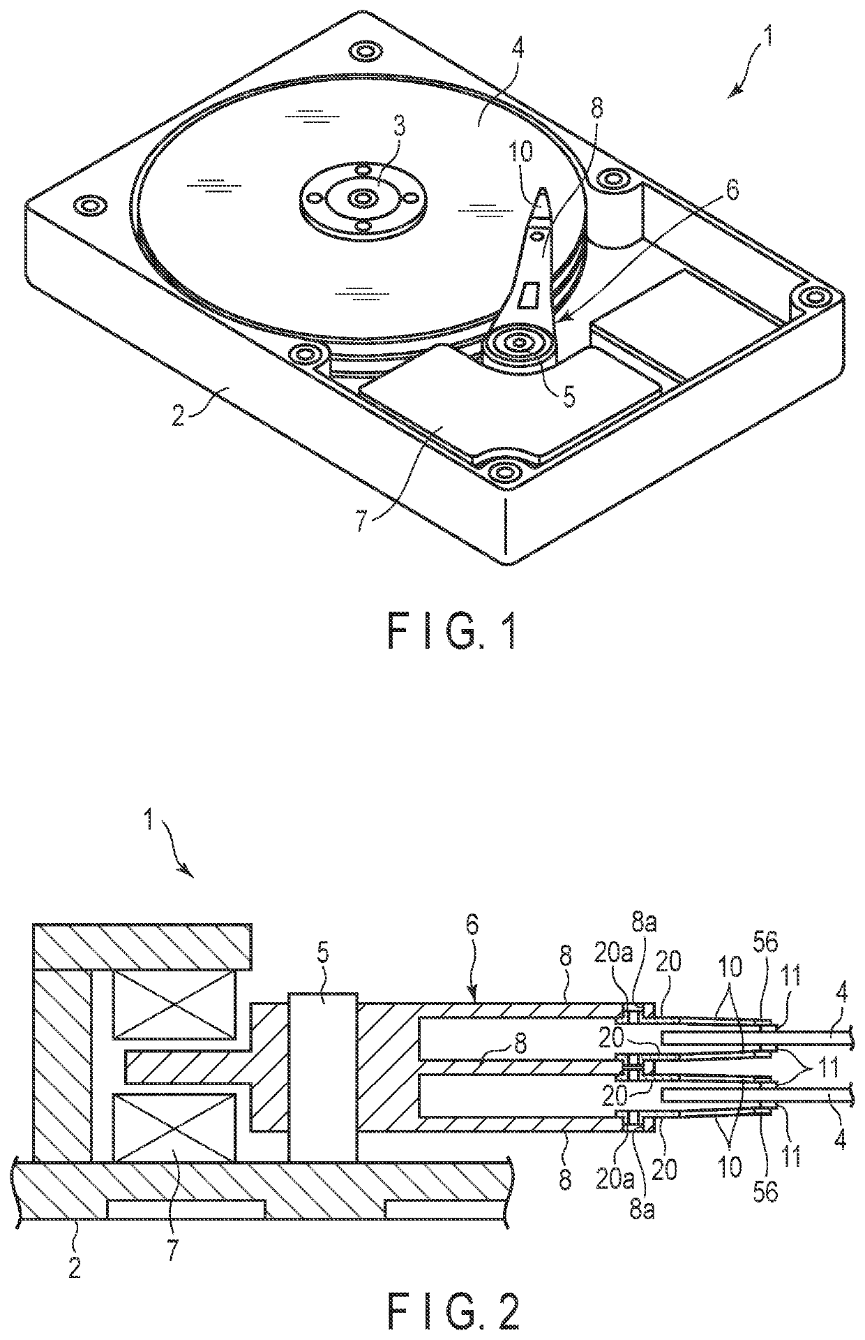
[0039]FIG. 1 is a schematic perspective diagram showing an example of a disk device (HDD) 1. The disk device 1 comprises a case 2, a plurality of disks 4 rotating around a spindle 3 at center, a carriage 6 pivotable around a pivot shaft 5 at center, and a positioning motor (a voice coil motor) 7 for driving the carriage 6. The case 2 is sealed by a lid (not shown).
[0040]FIG. 2 is a schematic cross-sectional view showing a part of the disk device 1. As shown in FIGS. 1 and 2, the carriage 6 is provided with a plurality of arms (carriage arms) 8. At a distal end portion of each arm 8, a suspension 10 is attached. At a distal end portion of each suspension 10, a slider 11, which constitutes a magnetic head, is provided. As a disk 4 rotate at high speed, air flows in between the disk 4 and the slider 11, thereby forming an air bearing.
[0041]When the carriage 6 is pivoted by the positioning motor 7, the suspension 10 moves along a diametrical direction of the disk 4 and thus the slider 1...
second embodiment
[0086]FIG. 11 is a schematic plan showing a part of a suspension 10 according the second embodiment. This suspension 10 is different from that of the example shown in FIG. 7 in that the first outrigger 51 does not comprise a first folded portion 51g, and further the second outrigger 52 does not comprise the second folded portion 52g.
[0087]From the point of view that the outriggers 51 and 52 are appropriately attached to the damper members 82 and 92, respectively, to increase the damping force, it is preferable to, for example, provide two folded portions for each of the outriggers 51 and 52 as in the case of the first embodiment, thereby increasing the contact area between the damper members 82 and 92 and the folded portions. Note that it is also possible to inhibit swinging of the flexure 22 even with the structure of this embodiment that the first outrigger 51 comprises one first folded portion 51f and the second outrigger 52 comprises one second folded portion 52f.
[0088]The fir...
third embodiment
[0090]FIG. 12 is a schematic plan showing a part of a suspension 10 according to the third embodiment. This suspension 10 is different from that of the example shown in FIG. 7 in the positions of the first folded portions 51f and 51g and the second folded portions 52f and 52g.
[0091]In an example shown in FIG. 12, the positions of the first folded portions 51f and 51g are displaced along the longitudinal direction X (or an extending direction of the first proximal end arm 51b). More specifically, the first folded portion 51f is located bent portion 51e and the first proximal end portion 51a and the first folded portion 51g in located between the first bent portion 51e and the first distal end arm 51c (shown in FIG. 5).
[0092]Similarly, the positions of the second folded portions 52f and 52g as well are displaced along the longitudinal direction X (or an extending direction of the second proximal end arm 52b). More specifically, the second folded portion 52f is located between the sec...
PUM
 Abstract
Description
Claims
Application Information