
Load distribution system and load distribution method

Pending Publication Date: 2021-09-23
NIPPON TELEGRAPH & TELEPHONE CORP
View PDF0 Cites 0 Cited by
  • Summary
  • Abstract
  • Description
  • Claims
  • Application Information

AI Technical Summary

Benefits of technology

The aim of this disclosure is to quickly and correctly determine the flow characteristics of a system or process.

Problems solved by technology

For example, when the packet transfer apparatus is achieved by a network virtualization technology, bps may be limited by a line rate of a physical Network Interface Card (NIC), and pps may be limited by a packet processing speed of software such as an Operating System (OS) or an application.
Thus, when the traffic of the VoIP, the telemetering, or the like is concentrated, enough transfer capacity for the amount of data is retained, whereas the transfer capacity for the number of packets is lacked.

Method used


Image

  • Load distribution system and load distribution method
  • Load distribution system and load distribution method
  • Load distribution system and load distribution method

Examples


example 1

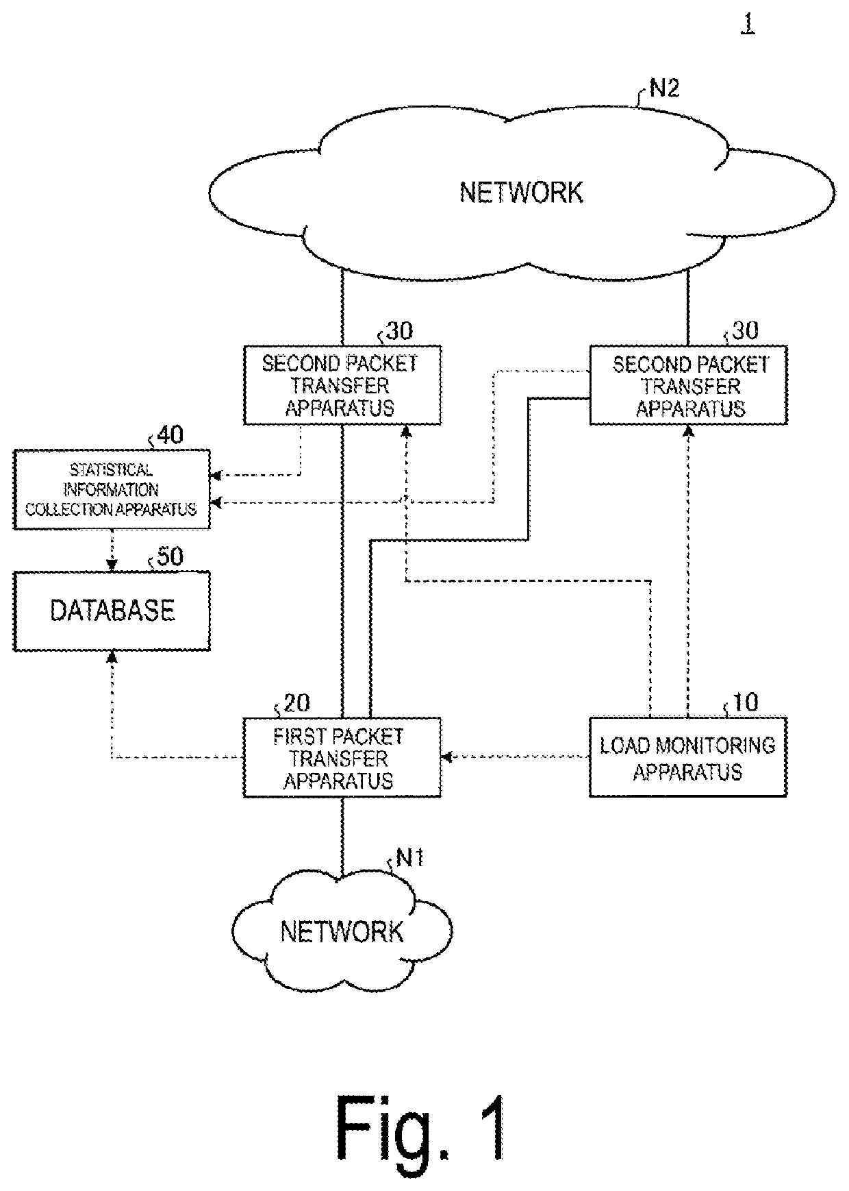
[0034]Hereinafter, Example 1 of the load balancing system 1 according to the embodiments of the present invention will be described below.

[0035]Functional Configuration

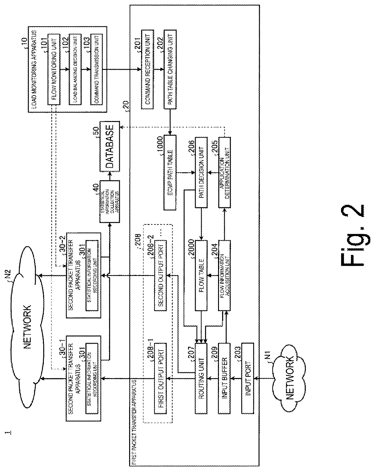
[0036]First, a functional configuration of the load balancing system 1 according to Example 1 will be described with reference to FIG. 2. FIG. 2 is a diagram illustrating an example of the functional configuration of the load balancing system 1 according to Example 1.

[0037]As illustrated in FIG. 2, the load monitoring apparatus 10 according to Example 1 includes a flow monitoring unit 101, a load balancing decision unit 102, and a command transmission unit 103.

[0038]The flow monitoring unit 101 monitors the traffic flows of these second packet transfer apparatuses 30 for the amount of data (bps) and the number of packets (pps) by using the statistical information of the second packet transfer apparatus 30. That is, the flow monitoring unit 101 obtains the amount of data (bps) and the number of packets (pps) as a monit...

example 2

[0130]When the use of a server that transmits and receives the packet is changed over time, the flow characteristics are changed even though the destination information is the same. To cope with such a situation, in Example 2, the “counter for flow characteristics” is stored in the database 50 in a plurality of divided periods.

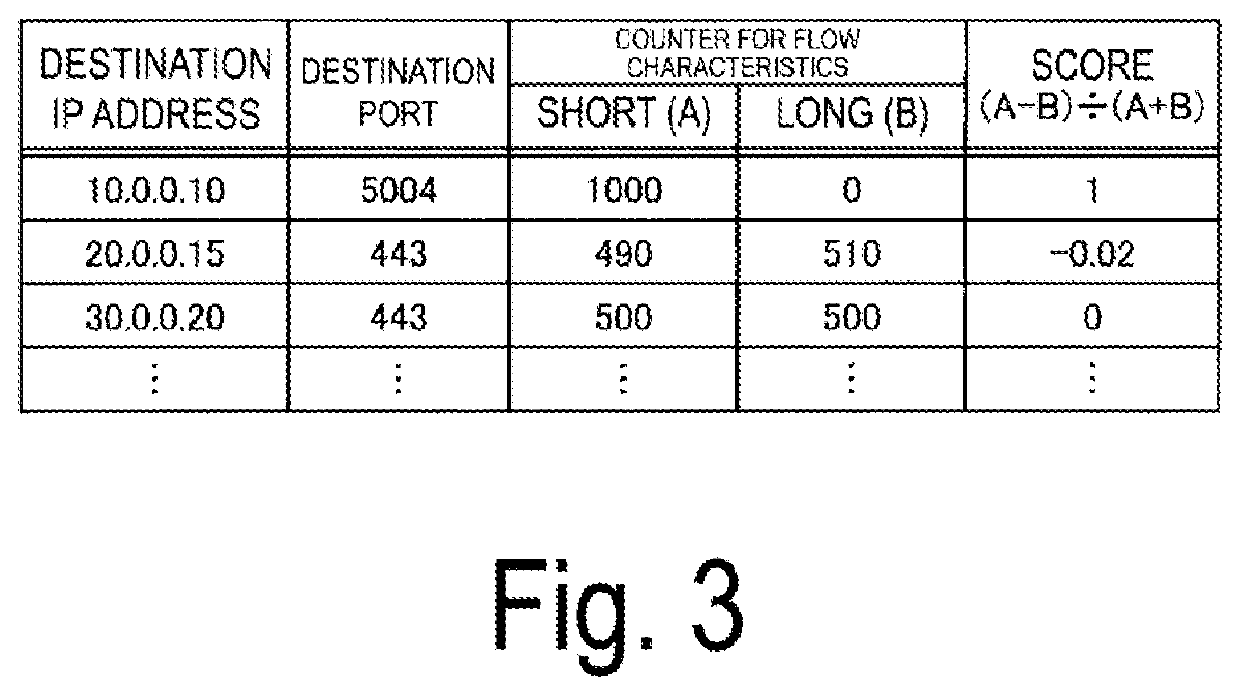
[0131]FIG. 9 is a diagram showing an example of the database 50 according to Example 2. As shown in FIG. 9, the “counter for flow characteristics” is divided into a counter that counts information from zero to two months ago, a counter that counts information from one to two months ago, and a counter that counts information from two to three months ago. Although the period is one month in FIG. 9, the period may be two weeks or any time unit such as two months. The “counter for flow characteristics” has a weighting factor used to calculate the “score” for each period.

[0132]The “score” is calculated as follows by using a value (A) of the short counter, a value (...


PUM


Abstract

A storage unit configured to store information regarding flow characteristics indicating whether a flow constituted by a packet is a flow having a tendency to have a large number of short packets or a flow having a tendency to have a large number of long packets in association with destination information of the packet, a determination unit configured to, in a case where an input port receives a packet, determine flow characteristics of a flow constituted by the packet on the basis of the storage unit, and an output unit configured to output the packet received by the input port to a packet transfer apparatus in a load state indicating that a load due to the flow of the flow characteristics is light among a plurality of packet transfer apparatuses according to the flow characteristics determined by the determination unit are provided.

Description

TECHNICAL FIELD[0001]The present invention relates to a load balancing system and a load balancing method.BACKGROUND ART[0002]A technology for balancing loads of packet transfer apparatuses such as routers has been known. For example, a technology for balancing loads of packet transfer apparatuses by preparing, as transfer destinations of packets, a plurality of packet transfer apparatuses and a plurality of transfer paths and equally applying traffic to these transfer paths has been known. A technology called Equal Cost Multi Path (ECMP) or ECMP routing has been known as such load balancing technologies. The ECMP is a load balancing technology for equally applying the traffic to the transfer paths at equal cost among the plurality of transfer paths.[0003]A technology for monitoring an output buffer of an output physical port of the packet transfer apparatus and switching the transfer paths when the amount of usage of the output buffer or a packet flow exceeds a threshold in the loa...

Claims


Application Information

Patent Timeline
IPC IPC(8): H04L12/851H04L12/803
CPCH04L47/2441H04L47/122H04L47/125H04L47/2483H04L47/24
Inventor KIMURA, AKIHIROKAWANO, SHINYATSUCHIYA, HIDEOOKADA, AKIHIROMIYAMOTO, KATSUMA
Owner NIPPON TELEGRAPH & TELEPHONE CORP
Learn More