Assembly method using assembly tool

a technology of assembly tool and assembly port, which is applied in the direction of fuel cell, collector/separator, fuel cell details, etc., can solve the problems of component dropping into these connection ports or contaminating these connection ports, and achieve the effect of reducing the contamination of such a connection por

a technology of assembly tool and assembly port, which is applied in the direction of fuel cell, collector/separator, fuel cell details, etc., can solve the problems of component dropping into these connection ports or contaminating these connection ports, and achieve the effect of reducing the contamination of such a connection por

US20210305593A1Active Publication Date: 2021-09-30HONDA MOTOR CO LTD

Image

  • Assembly method using assembly tool
  • Assembly method using assembly tool
  • Assembly method using assembly tool

Examples


Embodiment Construction

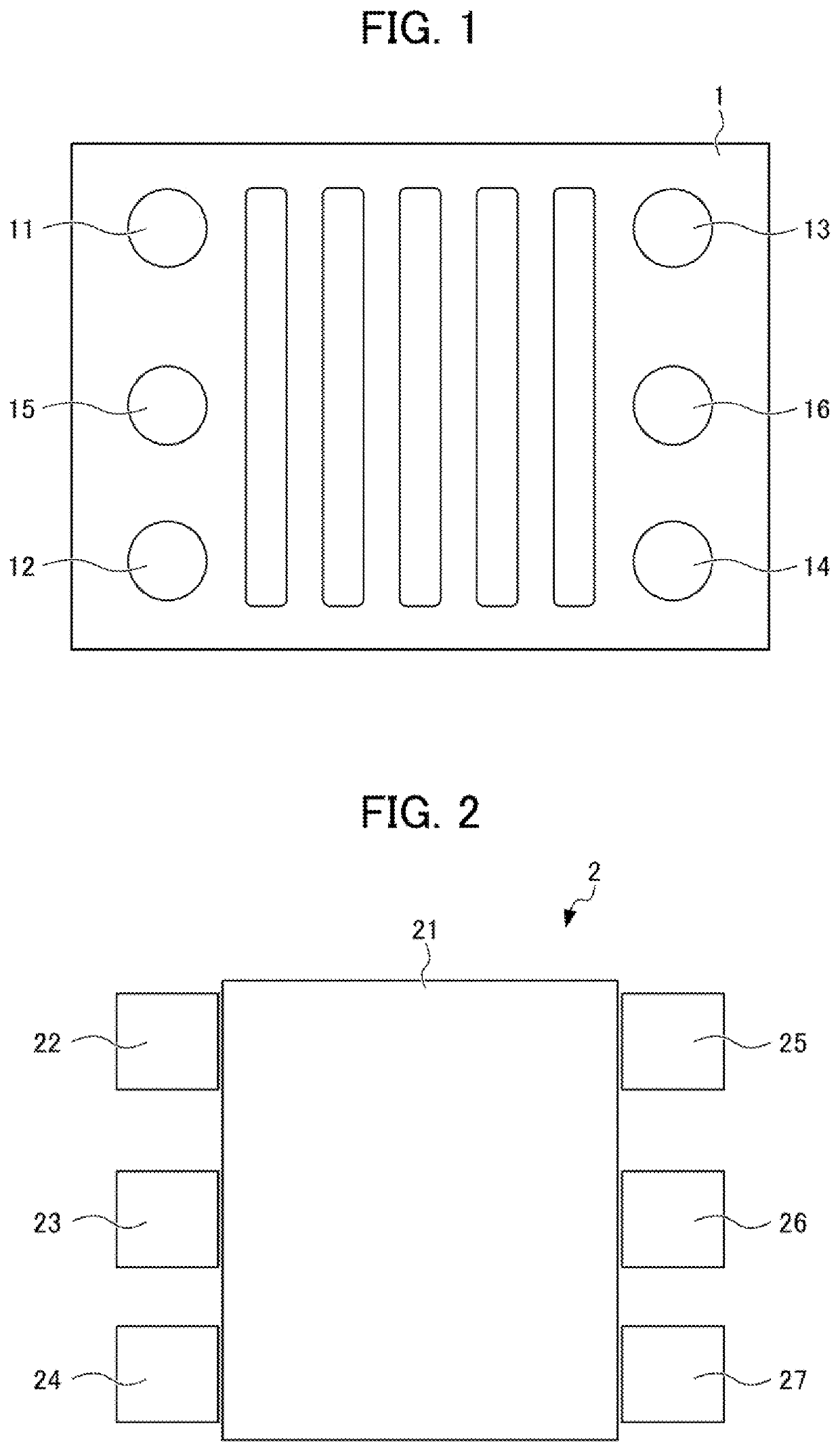
[0020]FIG. 1 is a plan view of a fuel-cell stack. An assembly tool according to one embodiment of the present invention is used when various components such as joints of reaction gas pipes or coolant water pipes are each assembled to a plurality of connection ports 11 to 16 provided at an upper surface of a fuel-cell stack 1 and communicating with a plurality of communication holes.

[0021]As shown in FIG. 1, the connection ports 11 to 16 communicating with the plurality of communication holes are formed at the upper surface of the fuel-cell stack 1. Any of the connection ports 11 to 14 through which reaction gas (hydrogen H2, oxygen O2) flows in or out is arranged at a corresponding one of four corners of the fuel-cell stack 1, and is provided to open upwardly. Any of these connection ports 11 to 14 communicates with a corresponding one of reaction gas flow paths formed in the fuel-cell stack 1.

[0022]Each of the connection ports 15, 16 through which coolant water flows in or out is a...


PUM

PropertyMeasurementUnit
transparentaaaaaaaaaa
sizeaaaaaaaaaa

Abstract

Provided is an assembly method using an assembly tool used when a component is assembled to each of a plurality of connection ports to provided at an upper surface of a fuel-cell stack and communicating with a plurality of communication holes. The assembly tool includes a base portion positioned on the upper surface of the fuel-cell stack and a plurality of covering portions covering the plurality of connection ports. Each of the plurality of covering portions is, relative to the base portion, provided movably between a covering position for covering a corresponding one of the connection ports and a non-covering position accessible to a corresponding one of the connection ports.

Description

[0001]This application is based on and claims the benefit of priority from Japanese Patent Application No. 2020-058117, filed on 27 Mar. 2020, the content of which is incorporated herein by reference.BACKGROUND OF THE INVENTIONField of the Invention[0002]The present invention relates to an assembly method using an assembly tool.Related Art[0003]Typically, one configured such that a plurality of holes communicating with an opening and opening to the outside is formed at an end plate of a fuel cell arranged at at least one end portion in a stacking direction and can be closed with a plug member has been disclosed (see, e.g., Japanese Unexamined Patent Application, Publication No. 2011-3348).[0004]The holes described herein function as connection ports for various components, and various components are assembled to these holes. Assembly of the component to each connection port is sequentially performed for each connection port.[0005]Patent Document 1: Japanese Unexamined Patent Applica...

Claims


Application Information

Patent Timeline
30 Sep 2021
Publication
US20210305593A1
IPC
H01M8/0202; H01M8/2404; H01M8/2475
CPC
H01M8/0269; H01M8/2475; H01M8/2404; B25B11/02; Y02E60/50
Inventors
HARADA, KEN; SHIMOMURA, YO