Touch panel and method for producing the same

a technology of touch panel and conductive layer, which is applied in the field of touch panel, can solve the problems of poor characteristics of transparent conductive layer, weakened strength of joint, and lack of uniform distribution of resistance value, and achieve uniform transparent conductive layer, reduce the effect of deterioration of characteristics caused by connection treatment, and facilitate the formation of the

Inactive Publication Date: 2010-09-16
TDK CORPARATION
View PDF0 Cites 8 Cited by
  • Summary
  • Abstract
  • Description
  • Claims
  • Application Information

AI Technical Summary

Benefits of technology

[0014]This method for producing a touch panel can satisfactorily produce a touch panel according to the invention having lead sections integrally formed with the electrode members. In addition, since the electrode members are formed with pre-formed lead sections in this method, there is no need for the high temperature treatment required when a connecting FPC or the like is provided afterwards. Deterioration in the characteristics caused by treatment for connection is thus drastically reduced.
[0015]In the production method of the invention, the transparent conductive layer is preferably formed by transfer or coating of a transparent conductive layer-forming material on the transparent base. This will allow a uniform transparent conductive layer to be formed more easily, and will also facilitate formation of the transparent conductive layer along the shapes of the lead sections when lead sections are provided by pre-working of the transparent base.
[0016]The extraction electrodes are preferably formed by coating the extraction electrode-forming material on the side of the transparent conductive layer in the electrode member opposite the transparent base side. This will facilitate formation of the extraction electrodes in the desired shapes, and is advantageous for forming extraction electrodes that lead out through the lead sections.
[0017]The extraction electrodes that lead out through the lead sections may also be formed by dipping the lead sections in the extraction electrode-forming material. This will permit formation of extraction electrodes on both sides of the lead sections in a more convenient manner, and will allow the extraction electrodes to be more easily led out to the transparent base side of the lead sections.
[0018]According to the invention it is possible to provide a touch panel that exhibits high strength at joints with external circuits, and that does not require high-temperature treatment for formation of the joints, as well as a method for producing it.

Problems solved by technology

However, since connection with an FPC requires connection of the FPC with the transparent conductive layer, the strength of the joint tends to be weakened.
In addition, connection of the FPC usually requires treatment at relatively high temperature, and high-temperature treatment can cause expansion of the transparent base and cracking of the transparent conductive layer, thereby potentially resulting in poor characteristics of the transparent conductive layer, which may include a lack of uniform distribution of the resistance value in the in-plane direction.

Method used


Image

  • Touch panel and method for producing the same
  • Touch panel and method for producing the same
  • Touch panel and method for producing the same

Examples


Embodiment Construction

[0022]Preferred embodiments of the invention will now be explained with reference to the accompanying drawings. Throughout the explanation of the drawings, corresponding elements will be referred to by like reference numerals and will be explained only once. Also, the dimensional proportions depicted in the drawings are not necessarily limitative.

[0023]The construction of a touch panel according to a preferred embodiment will be explained first.

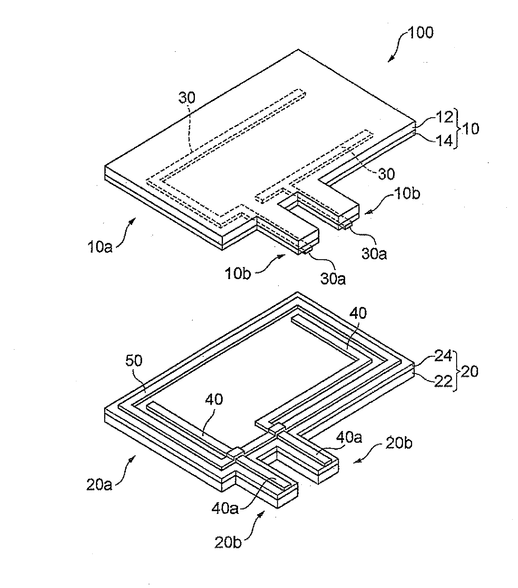
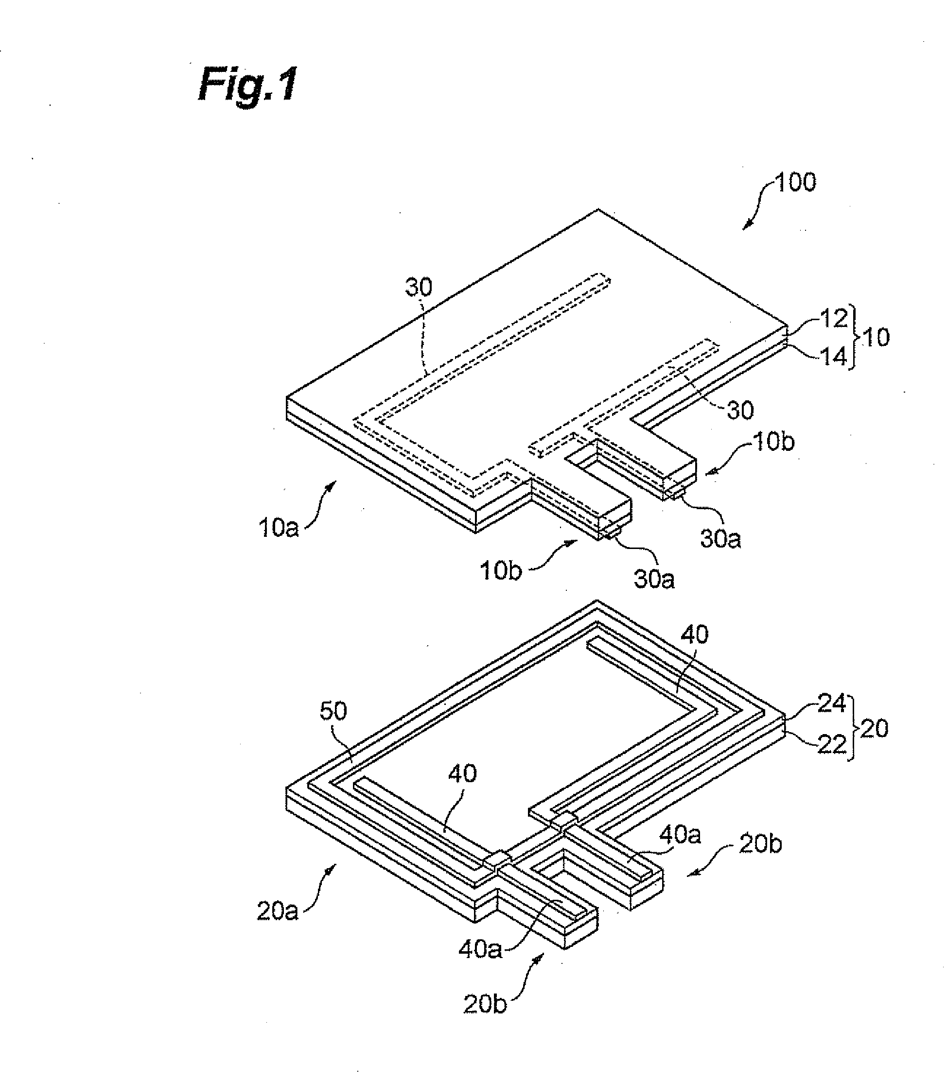
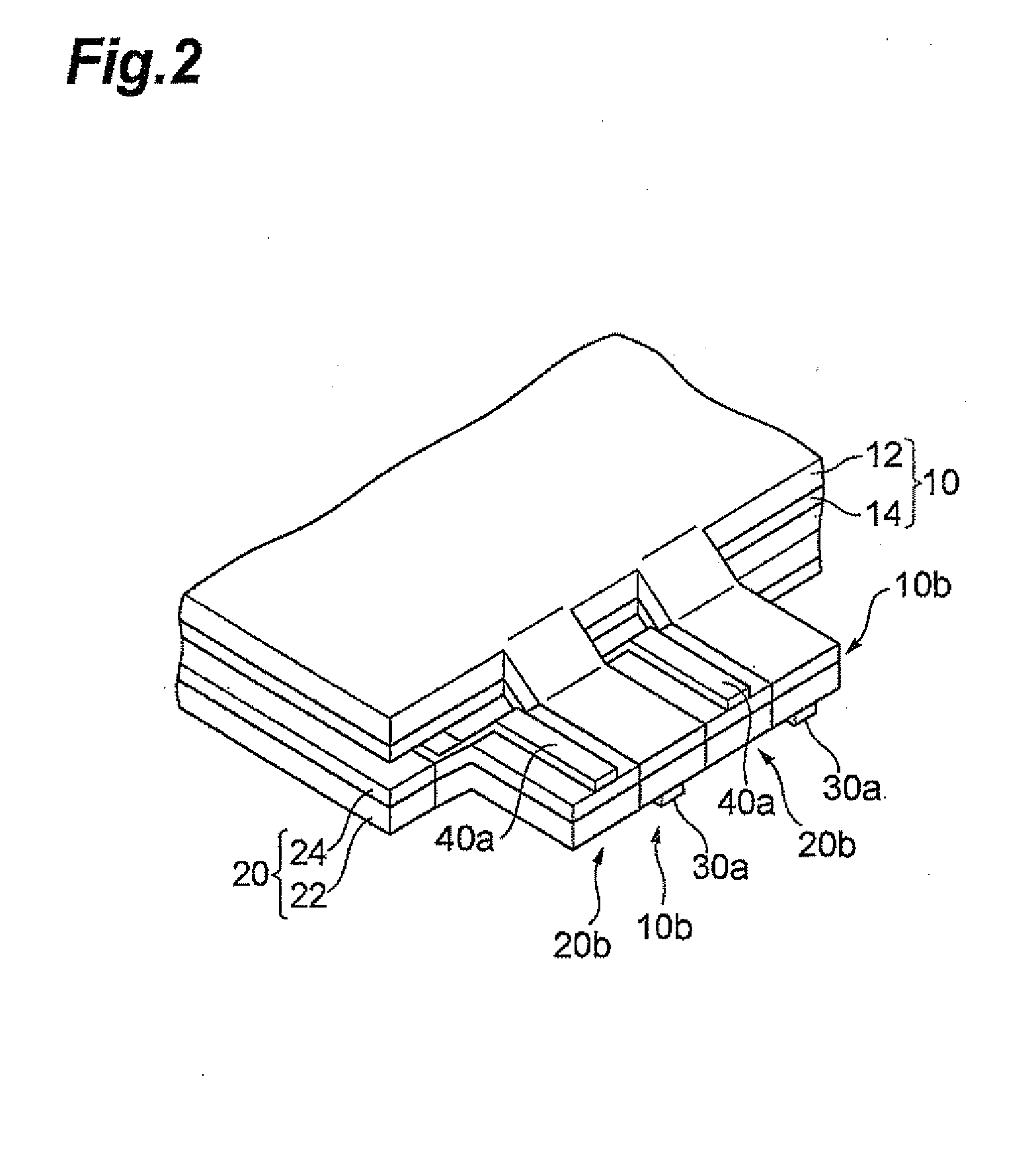
[0024]FIG. 1 is an exploded perspective view showing a touch panel according to the preferred embodiment. The touch panel 100 shown in FIG. 1 has a structure wherein an upper electrode member 10 comprising a transparent conductive layer 14 laminated on a transparent base 12 and a lower electrode member 20 comprising a transparent conductive layer 24 laminated on a transparent base 22 are situated in a mutually opposing manner with their transparent conductive layers 14, 24 facing each other.

[0025]The transparent bases 12, 22 are composed of a...


PUM

PropertyMeasurementUnit
transparentaaaaaaaaaa
transparent conductiveaaaaaaaaaa
flexibleaaaaaaaaaa

Abstract

The invention provides a touch panel that exhibits high strength at the joints with external circuits, and that does not require high-temperature treatment for formation of the joints. The touch panel of the invention comprises a pair of electrode members, each having a construction with a transparent base and a transparent conductive layer laminated on the transparent base, situated separate and opposing each other with their transparent conductive layers facing, wherein the electrode member has a body section and lead sections formed by protrusions of the transparent base and transparent conductive layer from an edge of the body section, and a pair of extraction electrodes are formed on the side of the transparent conductive layer opposite the transparent base, the pair of extraction electrodes opposing each other in the body section and each extending to the lead sections.

Description

BACKGROUND OF THE INVENTION[0001]1. Field of the Invention[0002]The present invention relates to a touch panel and to a method for producing it.[0003]2. Related Background Art[0004]Resistance film-type touch panels are known that have a structure with a pair of electrode members, each comprising a transparent conductive layer on a transparent base, laid together so that the transparent conductive layers are facing each other across a spacer or the like. In such touch panels, one of the electrode members is pressed to contact the other electrode member and create current between the transparent conductive layers, thereby allowing detection of the location that was pressed.[0005]Such touch panels require connection of the transparent conductive layer with an external circuit for detection of current.[0006]The connection has conventionally been made using a flexible printed circuit board (FPC) (see Japanese Unexamined Patent Publication No. 2003-29930 and Japanese Unexamined Patent Pub...

Claims


Application Information

Patent Timeline
Patent Type & Authority Applications(United States)
IPC IPC(8): G06F3/041H05K3/10
CPCY10T29/49155G06F3/045
Inventor INABA, KAZUHISAYASUDA, NORIYUKIMASHIMO, MASUTATSU
Owner TDK CORPARATION
Why Eureka
Try Eureka