Connector having shunt structure and shunt device thereof
a technology of shunt structure and shunt device, which is applied in the direction of coupling device connection, coupling contact member, securing/insulating coupling contact member, etc., can solve problems such as power loss, and achieve the effect of saving a space of an electronic devi
- Summary
- Abstract
- Description
- Claims
- Application Information
AI Technical Summary
Benefits of technology
Problems solved by technology
Method used
Image

Examples
first embodiment
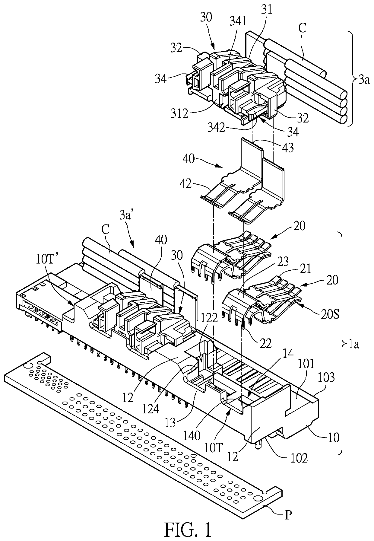
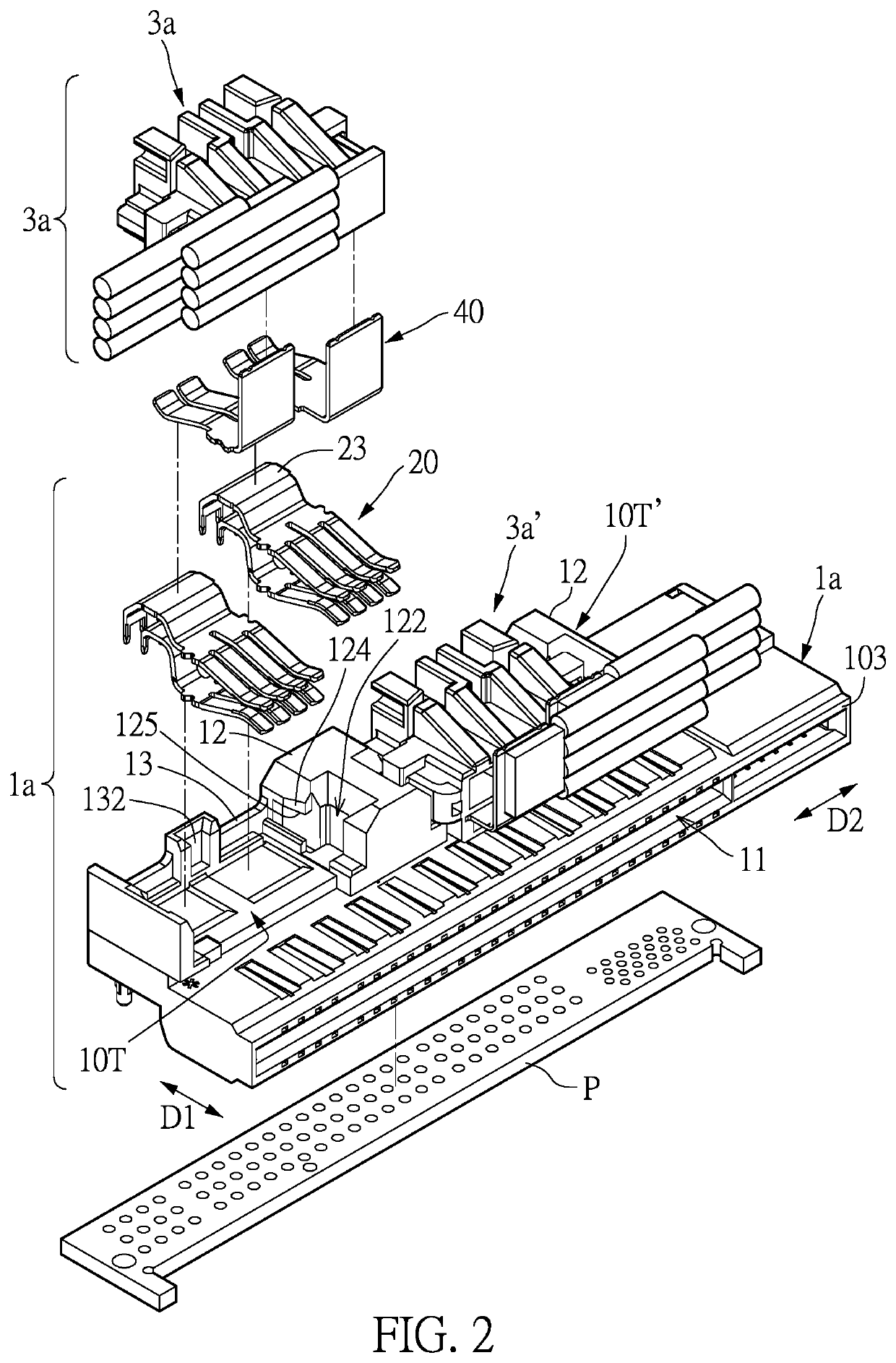
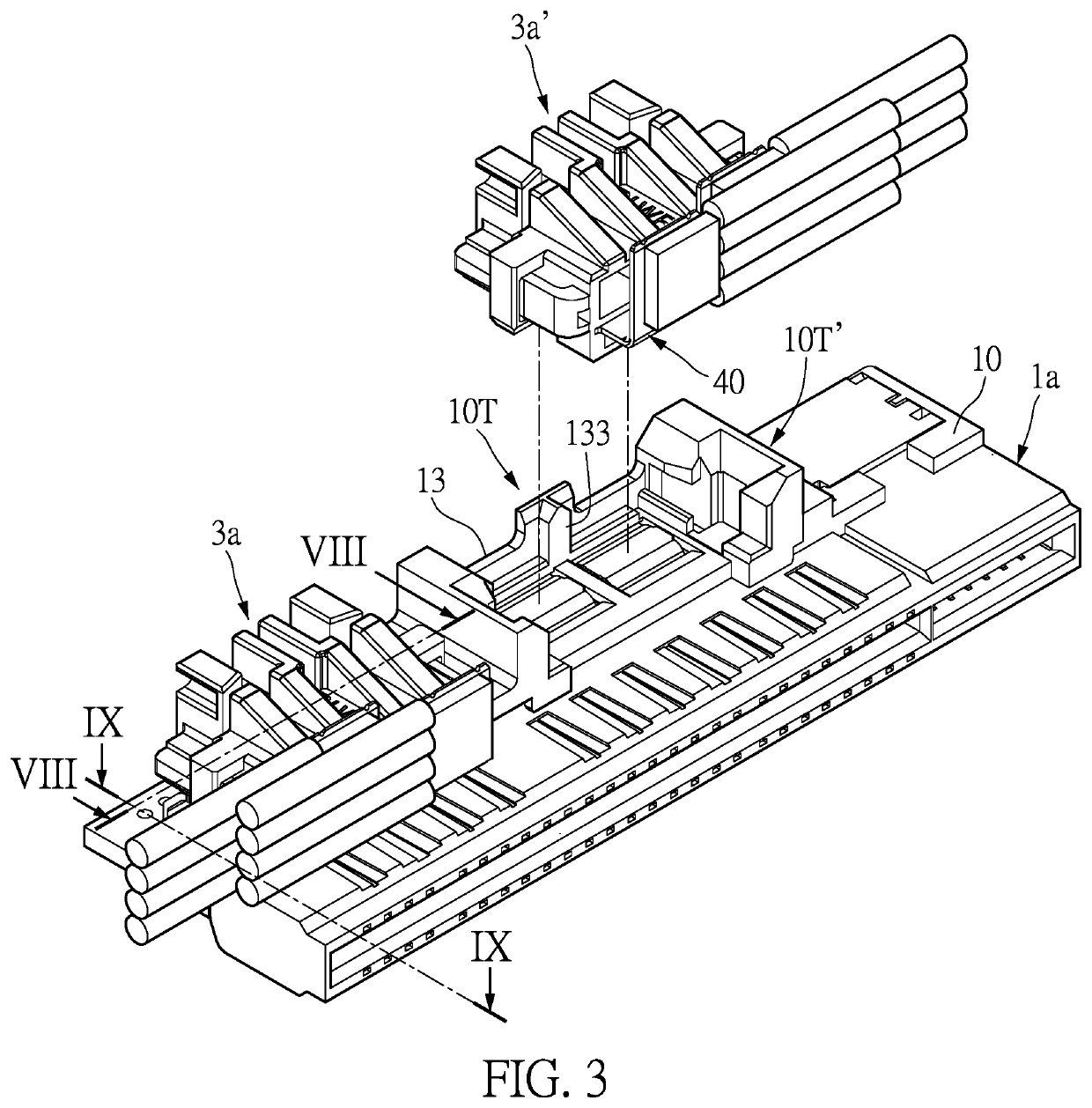
[0047]Referring to FIG. 1 to FIG. 3, a first embodiment of the present disclosure provides a connector assembly having a shunt structure, which includes a first connector 1a, a second connector 3a, and a third connector 3a′. The first connector 1a includes a first insulating housing 10, a plurality of first electrical terminals 20, and two adapter sockets 10T, 10T′. The first insulating housing 10 has a first side surface and a second side surface. The first side surface is rectangular in shape, and a length direction of the first side surface is parallel to a second direction D2 (as shown in FIG. 2). The first side surface has a plug side 103 that provides a plug input interface, so as to be electrically connected to a matching component (e.g., a power supply component). The second side surface has an output interface, which is used to output electric current and / or signals provided by the matching component. The first connector 1a may be called a connector having a shunt structure...
second embodiment
[0070]Referring to FIG. 10 to FIG. 15, a second embodiment of the present disclosure provides a connector assembly having a shunt structure, which includes a first connector 1b and a second connector 3b. The first connector 1b includes the first insulating housing 10 and a plurality of first power terminals 20′. Each of the first power terminals 20′ is used to conduct an electric current which is greater than or equal to 1 A at its maximum current. The second connector 3b includes the second insulating housing 30. What is different from the previous embodiment is that the second connector 3b of the present embodiment is obliquely inserted into the adapter socket 10T along a direction that is oblique to a top surface of the first connector 1b. The guide rail122 of the limiting side wall 12 is roughly L-shaped or semi-U shaped. The clamping portion 124 is formed at a front end of the limiting side wall 12 that is near the lateral wall 13. The lower surface of the clamping portion 124 ...
third embodiment
[0075]Referring to FIG. 16, a third embodiment of the present disclosure provides a connector assembly having a shunt structure, which includes a first connector 1c and a second connector 3c. The first connector 1c includes the first insulating housing 10 and the plurality of first electrical terminals 20. The second connector 3c includes the second insulating housing 30.
[0076]The guide block 32 of the second insulating housing 30 and the fastening portion 342 are protrudingly formed on two side surfaces. What is different from the previous embodiment in terms of structural design is that the guide block 32 is located at the front end of the second insulating housing 30, and is roughly L-shaped and faces outward. The fastening portion 342 exhibits an elastic arm shape, has a protrusion protruded outward, and is near the rear end of the second insulating housing 30. That is to say, the guide block 32 and the fastening portion 342 located on the same side surface are near another two ...
PUM
 Abstract
Description
Claims
Application Information
 - R&D Engineer
- R&D Manager
- IP Professional
- Industry Leading Data Capabilities
- Powerful AI technology
- Patent DNA Extraction
Browse by: Latest US Patents, China's latest patents, Technical Efficacy Thesaurus, Application Domain, Technology Topic.
© 2024 PatSnap. All rights reserved.Legal|Privacy policy|Modern Slavery Act Transparency Statement|Sitemap