Multi-path access network
a multi-path access and network access technology, applied in the direction of digital transmission, data switching networks, electrical equipment, etc., can solve the problems of reducing the overall network throughput, affecting the initial advantage of aggregated bandwidth, and not always predicting the processing power of gateway routers
- Summary
- Abstract
- Description
- Claims
- Application Information
AI Technical Summary
Benefits of technology
Problems solved by technology
Method used
Image
Examples
first embodiment
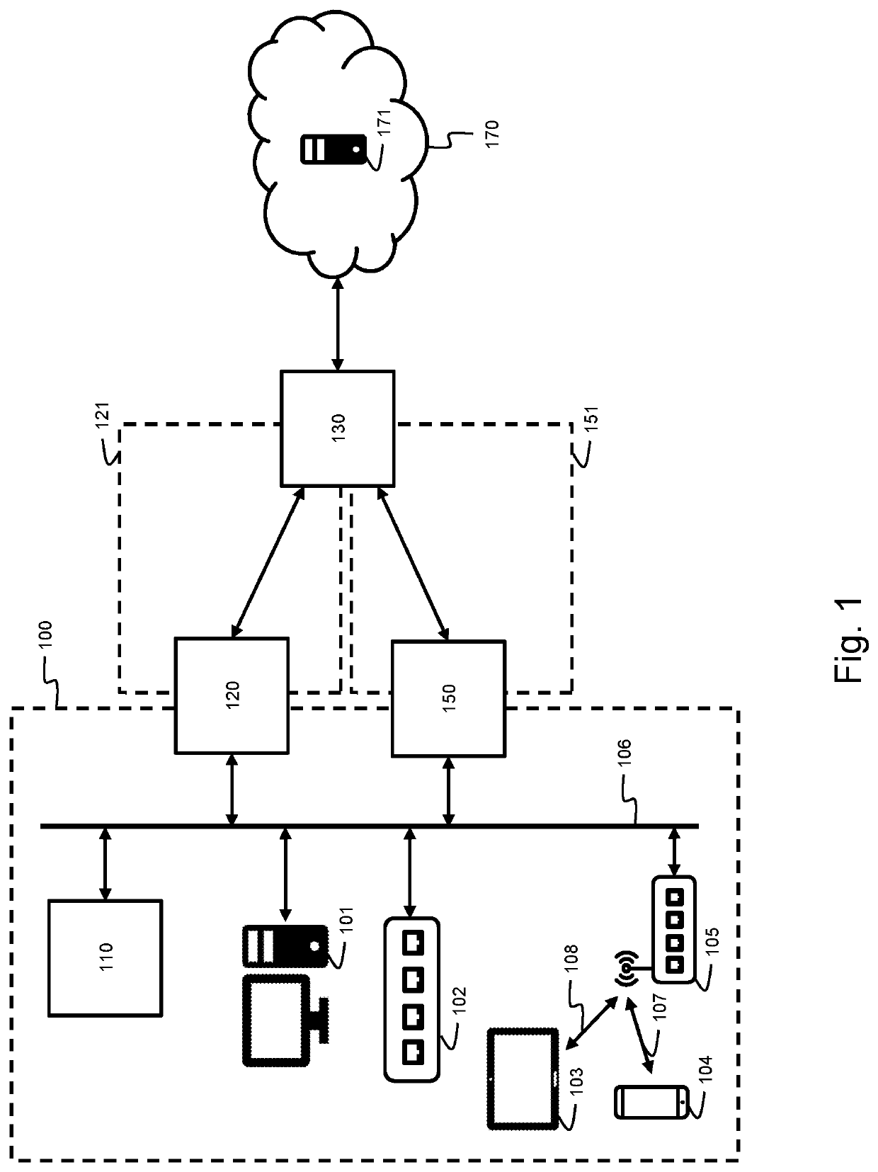
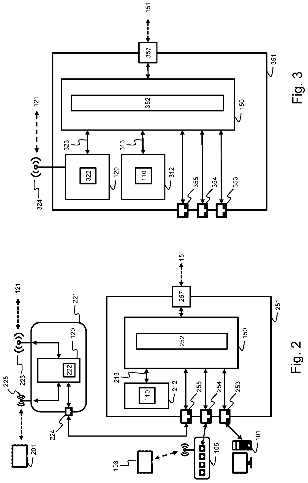
[0071]FIG. 2 illustrates a gateway router 251 comprising the first routing circuitry 150, and a second gateway router 221 comprising the second routing circuitry 120 according to a Gateway router 251 further comprises a wired communication interface 257 connectable to the first access network 151. Gateway router 251 may further comprise one or more wired communication interfaces 253, 254, 255 connectable to the LAN 100. A client 101 may then be directly connected to gateway router 251. The communication interfaces may also connect to a switch or wireless access point 105 to further connect to a client 103. Routing circuitry is further configured to perform different networking functions illustrated by box 252. These networking functions comprise a routing function for routing packets from the LAN 100 to the first access network 151 and vice versa; and a forwarding function for switching packets across the different connections within the LAN 100. Gateway router 251 further comprise...
second embodiment
[0074]FIG. 3 illustrates a gateway router 351 comprising the first routing circuitry 150 according to a Gateway router 351 further comprises a wired communication interface 357 connectable to the first access network 151. Gateway router 351 may further comprise one or more wired communication interfaces 353, 354, 355 connectable to the LAN 100 in an analogous way as shown in FIG. 2. Routing circuitry 150 is further configured to perform different networking functions illustrated by box 352. These networking functions comprise a routing function for routing packets from the LAN 100 to the first access network 151 and vice versa; and a forwarding function for switching packets across the different connections with the LAN 100. Gateway router 351 further comprises a first internal networking interface 313 connected to an internal control circuitry 312. This way, control circuitry 312 is an addressable network component of the LAN 100. The control circuitry 312 is further configured to...
third embodiment
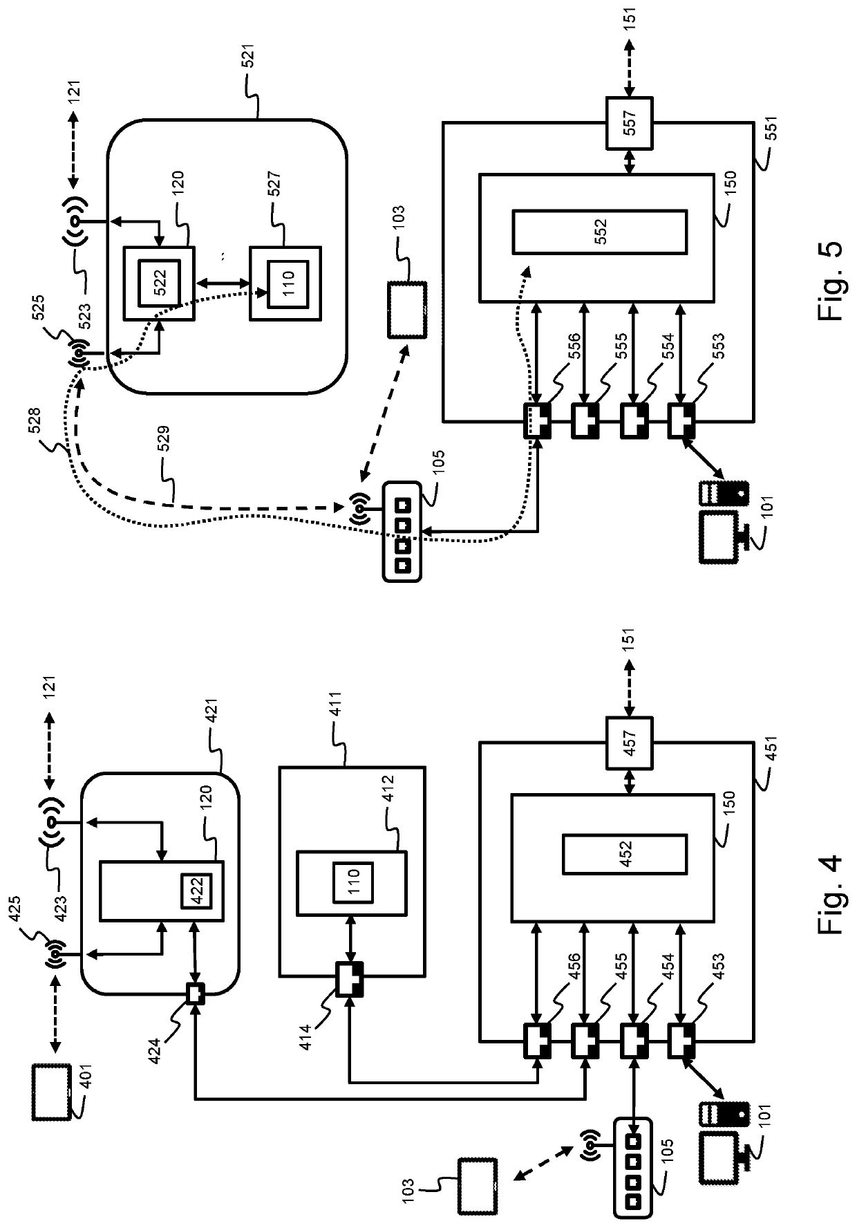
[0076][52]FIG. 4 illustrates a gateway router 451 comprising the first routing circuitry 150, a network device 411 comprising the multi-path agent 110 and a second gateway router 421 comprising the second routing circuitry 120 according to a Gateway router 451 further comprises a wired communication interface 457 connectable to the first access network 151. Gateway router 451 may further comprise one or more wired communication interfaces 453 to 456 connectable to the LAN 100 in an analogous way as shown in FIG. 2. Routing circuitry 150 is further configured to perform different networking functions illustrated by box 452. These networking functions 452 comprise a routing function for routing packets from the LAN 100 to the first access network 151 and vice versa; and a forwarding function for switching packets across the different connections with the LAN 100.
[0077][53] Gateway router 451 is further connectable over the LAN 100 to a multi-path networking device 411 further compris...
PUM
 Abstract
Description
Claims
Application Information
 - R&D
- Intellectual Property
- Life Sciences
- Materials
- Tech Scout
- Unparalleled Data Quality
- Higher Quality Content
- 60% Fewer Hallucinations
Browse by: Latest US Patents, China's latest patents, Technical Efficacy Thesaurus, Application Domain, Technology Topic, Popular Technical Reports.
© 2025 PatSnap. All rights reserved.Legal|Privacy policy|Modern Slavery Act Transparency Statement|Sitemap|About US| Contact US: help@patsnap.com


