Filter device

a filter device and filter technology, applied in the direction of separation process, dispersed particle separation, chemistry apparatus and processes, etc., can solve the problems of continuous production process cleaning that is not suitable for finer particles, production process must be interrupted, etc., and achieves the effect of convenient operation

Active Publication Date: 2021-10-14
LUFTECHNIK GRANSEE GMBH +1
View PDF3 Cites 0 Cited by
  • Summary
  • Abstract
  • Description
  • Claims
  • Application Information

AI Technical Summary

Benefits of technology

[0005]It is therefore an object of the present invention to provide a filter device for filtering particles from an air stream, which enables a filter element to be replaced without interrupting the process and which is easy to operate.
[0007]The filter device according to the invention has an insertion chamber closable by a door, from which the filter element can be fed to the flow channel, and an output chamber closable by a closure element, into which a filter element can be fed from the flow channel, wherein the closure element of the output chamber is locked in the closed position via a locking mechanism when the door on the insertion chamber is open, and the output chamber and the insertion chamber are connected to the same flow channel. This can prevent incorrect operation when replacing a filter element, since the closure element of the output chamber can only be opened when the door on the insertion chamber is closed. Therefore, the user must first insert a filter element into the insertion chamber and close the closure element before the closure element on the output chamber can then be opened. In this case, the locking mechanism is effective at the same shaft at which the insertion chamber, the flow channel and the output chamber are connected to each other and form a common shaft. The shaft may preferably be oriented vertically as a drop shaft, but orientation horizontally or in any other direction is also possible. The filter device can have several such shafts in succession in the direction of flow.
[0008]An opening is preferably formed between the insertion chamber and the flow channel, which can be closed by a movable cover. The opening can be released by the cover when the door on the insertion chamber is arranged in the closed position. This prevents both the opening and the door from being arranged in an open position, which leads to foreign air being sucked in at the filter device and has an impact on the production process, especially if it is a pressure-sensitive production process, for example in fiber production. To ensure that the door on the insertion chamber and the opening between the insertion chamber and the flow channel are not open at the same time, the door can be movable together with the cover to open and close the insertion chamber. A corresponding opening in the cover then releases the opening between the insertion chamber and the flow channel only when the sliding door is in a closed position.
[0011]According to a further embodiment according to the invention, the filter device has an insertion chamber which can be closed by a door and from which a filter element can be fed to the flow channel, and an output chamber which can be closed by a closure element and into which a filter element can be fed from the flow channel, wherein the flow channel comprises at least two filter elements arranged one behind the other in the direction of flow, which are coded by a different geometry and can each be inserted only into one of two adjacent insertion chambers of two or more adjacent insertion chambers. This ensures that only one insertion chamber is assigned to each filter element by a specific geometry, so that interchanging of the filter elements is ruled out. Particularly when different filter elements are used as coarse filters or fine filters, coding by means of a geometry can prevent another filter element from being inserted into a specific insertion chamber. Such coding can, for example, be formed by different widths, different thicknesses or other geometric designs, such as bevels, projections or pins.
[0012]Preferably, each door and / or each closure element can be positioned on the insertion chamber or the output chamber in a sealed manner via a circumferential seal. Particularly in production plants with pressure-sensitive production processes, an intake of foreign air at the filter device can thus be kept to a minimum.
[0013]Preferably, a cover can be inserted on the filter element, which covers a filter cake on the filter element, so that the unit consisting of filter element and cover can be removed from the output chamber. The cover can be used to close the filter element during the removal process, so that the separated particles forming the filter cake are held securely inside the filter element by the cover. For this purpose, the filter element can be designed as a filter cartridge, which has a circumferential frame around a filter surface. Furthermore, a latching or locking mechanism can optionally be provided on the cover, which can be latched or locked to the filter element, for example via a rotating part. Then the filter element can be removed from the output chamber via the cover, wherein the cover preferably comprises a handle element for this purpose, so that the user can only pull out the filter element after the cover has been fitted.

Problems solved by technology

However, such cleaning during the production process in continuous operation is poorly suited for finer particles.
The disadvantage of such a filter device, however, is that the production process must be interrupted in order to change the filter elements.

Method used


Image

  • Filter device
  • Filter device
  • Filter device

Examples


Embodiment Construction

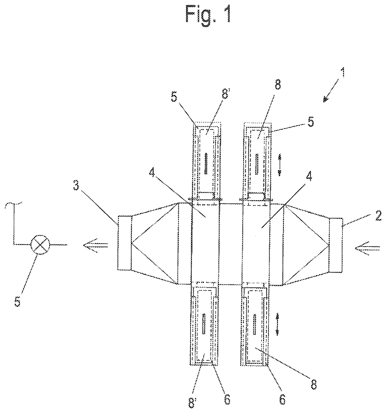
[0023]A filter device 1 is used for the filtration of an air flow, for example in a production plant for fibers or filaments or for the purification of combustion exhaust gases. The filter device 1 comprises an inlet channel 2, at which the air to be cleaned flows in, and an outlet channel 3, from which the cleaned air flows out. Between the inlet channel 2 and the outlet channel 3, one or more chambers are arranged in a flow channel 4, in which a filter element 8 or 8′ can be positioned.

[0024]In order to be able to change the filter element arranged in the flow channel 4 during operation, an insertion chamber 5 and an output chamber 6 are provided adjacent to the flow channel 4. In this case, the inlet channel 2 is connected to a chamber in the flow channel 4, which in turn is connected to the outlet channel 3. Such a shaft can be arranged one or several times in succession, as seen in the direction of flow, for example in order to use a filter element 8 as a coarse filter and a fi...


PUM

PropertyMeasurementUnit
timeaaaaaaaaaa
thicknessesaaaaaaaaaa
pressure-sensitiveaaaaaaaaaa

Abstract

A filter device for filtering particles from an air stream has an inlet channel through which the air to be purified flows, at least one filter element through which the air can flow and which is interchangeably held in a flow channel, and an outlet channel through which the purified air flows, an insertion chamber which can be closed by a door and from which a filter element can be fed to the flow channel, and an output chamber closable by a closure element, into which a filter element is feedable from the flow channel. The closure element of the output chamber is locked in the closed position via a locking mechanism when the door on the insertion chamber is opened and the output chamber and the insertion chamber are connected to the same flow channel.

Description

CROSS-REFERENCE TO RELATED APPLICATIONS[0001]This application claims priority under 35 USC 119 of German Application No. DE 10 2020 110 081.7, filed on Apr. 9, 2020, the disclosure of which is herein incorporated by reference.BACKGROUND OF THE INVENTION[0002]The present invention relates to a filter device for filtering particles from an air stream, comprising an inlet channel through which the air to be purified flows, at least one filter element through which the air can flow and which is replaceably held in a flow channel, and an outlet channel through which the purified air flows.[0003]For cleaning an air stream, drum filters are known in which a surface of the drum filter is cleaned via a suction nozzle, as is known from DE 28 02 369 A1. However, such cleaning during the production process in continuous operation is poorly suited for finer particles.[0004]DE 91 01 692 U1 discloses a filter device in an air channel system that can be replaced. For replacement, the filter device ...

Claims


Application Information

Patent Timeline
Patent Type & Authority Applications(United States)
IPC IPC(8): B01D46/42B01D46/00
CPCB01D46/4227B01D46/008B01D46/0004B01D46/0023B01D46/0005B01D46/0091B01D46/10B01D2271/02B01D46/90B01D46/56B01D46/88B01D46/62
Inventor MATHO, RAINERMUELLER, ANDREASRICKERTS, STEPHANCLAUSSEN, ERNSTPETERSEN, HAUKEKNOEDLER, FRANKDITTSCHER, SONJA
Owner LUFTECHNIK GRANSEE GMBH
Why Eureka
Try Eureka