Control module of an air treatment system of a utility vehicle

a control module and air treatment technology, applied in the direction of valve housings, braking systems, braking components, etc., can solve the problems of enabling the subsequent replacement of parts with considerable effort and accordingly complex design, and achieve the effect of reliably preventing unwelcome leakag

Pending Publication Date: 2021-10-21
WABCO GMBH
View PDF0 Cites 3 Cited by
  • Summary
  • Abstract
  • Description
  • Claims
  • Application Information

AI Technical Summary

Benefits of technology

[0025]According to a preferred design, a mounting surface of the control module is formed directly as a lateral surface of the module housing, or as a sub-region of a lateral surface. Therefore, the control module can be directly seated on, and pneumatically connected to, an air dryer by means of its module housing. In this case, pneumatic connections of the solenoid valves, i.e. in particular pneumatic connections of the armatures with, for example, suitable sealing surfaces, advantageously lie toward the mounting surface project freely beyond the mounting surface so that they are seated directly in corresponding pneumatic sockets of the air dryer when the control module is seated on the air dryer housing. Therefore, pneumatic connections and furthermore the sealing contact between the module housing and the air dryer unit can be established during installation.
[0026]In turn, a very compact construction is thus ensured, wherein undesired leakage caused by split lines etc. can also be reliably prevented as a result of the direct connection. This selected design is compact and robust with respect to mechanical shocks.
[0027]In addition t

Problems solved by technology

Such designs are accordingly often complex and only enable t

Method used


Image

  • Control module of an air treatment system of a utility vehicle
  • Control module of an air treatment system of a utility vehicle
  • Control module of an air treatment system of a utility vehicle

Examples


Embodiment Construction

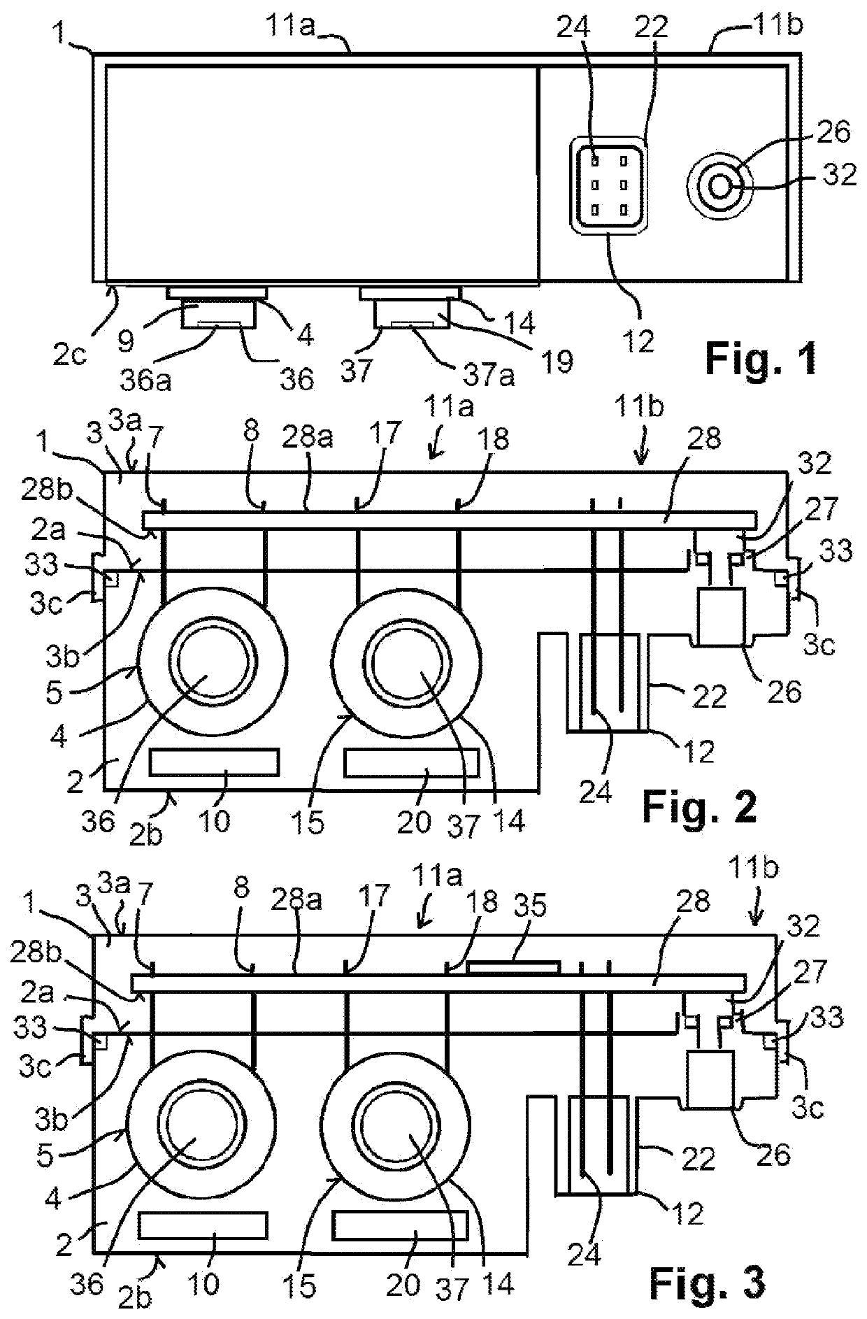
[0036]A control module 1 has, according to FIG. 1, 2, a module housing 2 formed as a die-cast body and a cover 3. A first solenoid valve 4 and a second solenoid valve 14 are cast in the module housing 2. The first solenoid valve 4 has a first coil 5, which is generally wound from a first copper wire, wherein the first coil is contacted via first connection pins 7, 8. A first armature 9, which is partially adjustable by the magnetic field of the first coil 5, is accommodated in the first coil 5. Furthermore, the first solenoid valve 4 generally has a first yoke 10 for closing the first magnetic field of the first coil 5, wherein the first yoke 10 can be seen in the section of FIG. 2 and generally extends to above and below the first coil 5.

[0037]The second solenoid valve 14 accordingly has a second coil 15 made from a second copper wire, second connection pins 17, 18 and a second armature 19 accommodated in the second coil 15, wherein the second magnetic field of the second coil 15 i...


PUM


Abstract

A control module for an air treatment system of a utility vehicle comprises the following: a first and second pneumatic magnetic valve having a first or second coil, connecting pins, and armatures accommodated in the coils, a circuit carrier, and a module housing that is cast from a plastic material, into which housing the coils are cast. The connecting pins project from a first side of the module housing and are electrically connected to the circuit carrier. A plug-in connection for receiving a connection plug is formed in the module housing, wherein the plug-in connection has plug-in pins, which extend through the module housing and are electrically connected to the circuit carrier. The module housing has a mounting surface having pneumatic connections for installation on an air dryer housing of an air dryer.

Description

CROSS-REFERENCE TO RELATED APPLICATIONS[0001]This application is the National Stage of International Application No. PCT / EP2019 / 070852, filed on 2 Aug. 2019, which claims priority to and all advantages of German Patent Application No. 10 2018 121 384.0, filed on 3 Sep. 2018, the contents of which are hereby incorporated by reference.FIELD OF THE DISCLOSURE[0002]The invention relates to a control module of an air treatment system of a commercial vehicle and such an air treatment system.BACKGROUND[0003]Control modules for air treatment systems can have different constructions for accommodating a few or multiple functional parts of the electropneumatic air treatment system.[0004]DE 10 2004 051 309 A1 describes an electronic control unit having a function logic circuit in which the solenoid valves and the microprocessor can also be accommodated.[0005]DE 10 333 610 B4 describes a module comprising solenoid valves and an ECU, which serves to control the air treatment and air suspension. D...

Claims


Application Information

Patent Timeline
IPC IPC(8): B60T17/00B60T17/02B60T17/04F15B13/08
CPCB60T17/004B60T17/02B60T17/04F15B13/0853F16K27/003F15B13/0842F15B13/085F15B13/086F15B13/0857F15B21/041F15B21/048F15B2211/615F15B2211/8855
Inventor DIEKMEYER, HEINRICHHEIDER, JOACHIMHILLBRING, DIRKTEICHMANN, ANDREAS
Owner WABCO GMBH
Why Eureka
Try Eureka