Truck mounted forklift

a forklift and truck body technology, applied in the direction of lifting devices, control devices, propulsion parts, etc., can solve the problems of increasing the weight of the forklift and mounting arrangement, further reducing the carrying capacity of the carrying vehicle, and reducing the overhang of the forklift, so as to avoid narrowing the distance, advantageously compact, and reduce the effect of overhang

Pending Publication Date: 2021-10-28
CARGOTEC ENG IRELAND LTD
View PDF0 Cites 0 Cited by
  • Summary
  • Abstract
  • Description
  • Claims
  • Application Information

AI Technical Summary

Benefits of technology

The invention is about a forklift that has a compact electric wheel motor assembly for its front wheels, which doesn't increase the width of the forklift or reduce its frame opening. This allows the forklift to pick up and put down heavy loads wider rearwards of the front wheels. Additionally, the forklift uses a 47:1 planetary gear box which reduces its speed and increases its torque output. The gearing ratio is the same for all the wheels. This results in a more powerful forklift that can handle larger loads.

Problems solved by technology

These TMFLs are of necessity very lightweight as any increase in forklift weight reduces the carrying capacity of the carrying vehicle which would otherwise be used for the transport of goods on the carrying vehicle.
Furthermore, any increase in weight of the forklift requires heavier tines and more robust mounting arrangements which in turn further increases the weight of the forklift and mounting arrangements and further reduces the carrying capacity of the carrying vehicle.
For these reasons, it is also not possible for TMFLs to be provided with counterweights as would commonly be found in other types of forklifts.
There are however a number of considerations and limitations particular to this TMFL configuration.
If the frame opening between the side bars is reduced, this will reduce the physical size of heavy goods that may be picked up, thereby reducing the usefulness of the forklift.
However, it is not possible to simply increase the frame opening between the side bars unchecked, as the total width of the forklift cannot protrude outwardly beyond the sides of the carrying vehicle during transit.
However, this is impractical as the majority of the weight of the TMFL would be located away from the driven rear wheel which would result in a TMFL that was difficult to manoeuvre and less effective in operation.
However, this requires a motor to drive the front wheel.
This problem becomes particularly acute in electric vehicles, as it is understood that the electric motor and associated gearing to drive the front wheel will take up significant space in the side bar, reducing the frame opening between the side bars.
As the dimensions of the side bar increase to accommodate the electric motor and gearing, not only does this increase the weight and the cost of the side bar, but this can also lead to a reduction of the TMFL's ground clearance, i.e. the distance between the underside of the side bar and the ground.
A reduction in ground clearance will negatively impact the TMFL's ability to mount obstacles such as kerbs and the like.
In addition to the foregoing, there are a number of other design limitations particular to TMFLs that should be taken into consideration.
Therefore, increases in the dimensions of the rear wheel assembly are also disadvantageous.
Furthermore, the greater the overhang, the greater the forces applied by the TMFL on the tines and mounting equipment.
This necessitates more robust, heavier tines and mounting equipment which is undesirable for the reasons outlined above.

Method used


Image

  • Truck mounted forklift
  • Truck mounted forklift
  • Truck mounted forklift

Examples


Embodiment Construction

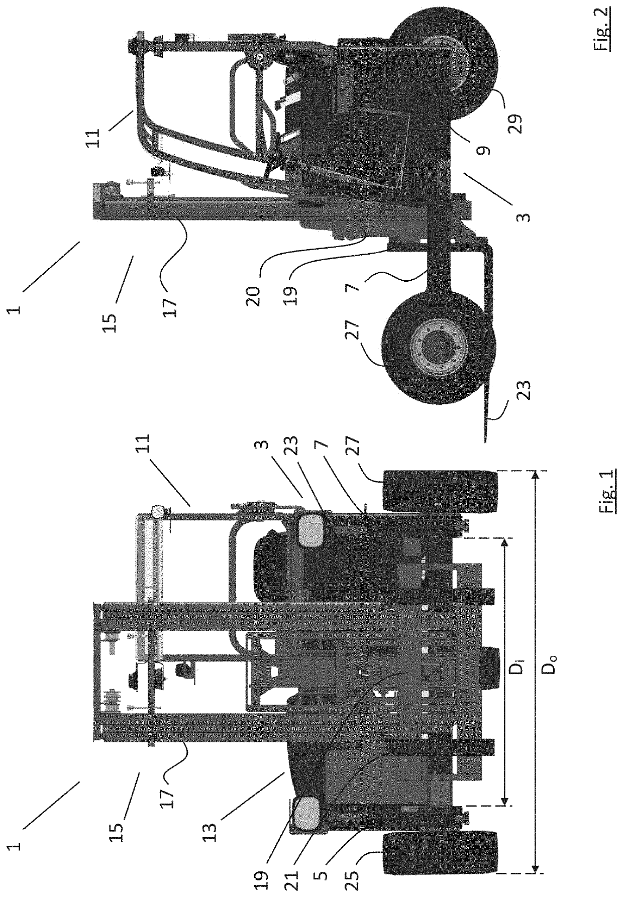
[0046]Referring to FIGS. 1 and 2, there is shown a truck mounted forklift (TMFL), indicated generally by the reference numeral 1, comprising a U-shaped chassis 3 having a pair of side bars 5, 7 and a rear cross bar 9 bridging the two side bars. A driver's station 11, a battery pack 13, and a lifting assembly 15 are mounted on the chassis. The lifting assembly comprises an upright mast 17 having a fork carriage 19 carrying a pair of forks 21, 23. The upright mast 17 is a multi-stage mast so that the forks 21, 23 are height adjustable up and down the mast and there is further provided a pantograph arrangement 20 to alter the reach of the forks. As an alternative to a pantograph arrangement, extensible forks could be provided. Indeed, the mast may also be mounted on a mast carriage slidable forwards and backwards along the U-shaped chassis.

[0047]There is further provided a pair of front wheels 25, 27, one at the forwardmost end of each of the side bars 5, 7, and a steerable rear wheel ...


PUM


Abstract

This invention relates to a truck mounted forklift (TMFL), more specifically an electrically powered TMFL. The TMFL comprises a U-shaped chassis having a pair of side bars bridged by a rear cross bar, a pair of front wheels, and a rear wheel. The TMFL further comprises a lifting assembly, a driver's station, and a battery pack mounted on the chassis. Each of the front wheels is provided with a dedicated electric wheel motor assembly. The electric wheel motor assemblies each comprise an interior permanent magnet (IPM) motor having a drive shaft, and a planetary gear box coupled to the IPM motor. The planetary gear box is mounted axially in-line with and is driven by the drive shaft. The IPM motor is mounted substantially internal the side bar and the planetary gear box is mounted substantially internal the bounds of the wheel rim. In this way, a very compact configuration of drive assembly for the front wheels is provided.

Description

RELATED APPLICATIONS[0001]This Application is based on and claims the benefit of priority from United Kingdom Patent Application No. 2006034.9, filed 24 Apr. 2020, the entire disclosure of which is incorporated herein by reference.TECHNICAL FIELD OF THE INVENTION[0002]This invention relates to a truck mounted forklift (TMFL). More specifically, the invention relates to an electric truck mounted forklift.BACKGROUND OF THE INVENTION[0003]TMFLs are a very useful type of forklift truck that may be mounted on the rear of a trailer and transported to and from a customer's premises. Once there, the TMFL may be used to load and unload goods to or from the trailer. Accordingly, the TMFL obviates the need for the customer to have access to, or own, their own forklift.[0004]These TMFLs are of necessity very lightweight as any increase in forklift weight reduces the carrying capacity of the carrying vehicle which would otherwise be used for the transport of goods on the carrying vehicle. Furthe...

Claims


Application Information

Patent Timeline
Patent Type & Authority Applications(United States)
IPC IPC(8): B66F9/075
CPCB66F9/07563B66F9/07509B66F9/07572B60K1/02B60K17/043B60K17/14
Inventor TURNBULL, KEVIN
Owner CARGOTEC ENG IRELAND LTD
Why Eureka
Try Eureka