Evaporation Device

Inactive Publication Date: 2021-10-28
WUHAN CHINA STAR OPTOELECTRONICS SEMICON DISPLAY TECH CO LTD
View PDF0 Cites 1 Cited by
  • Summary
  • Abstract
  • Description
  • Claims
  • Application Information

AI Technical Summary

Benefits of technology

[0024]The present disclosure proposes a disposition device which includes a primary chamber and two or more secondary chambers arranged on both sides of the primary chamber. The secondary chamber is configured to supply the disposition material in a disposition process. One or more of the secondary chambers serve as an alternative disposition source.

Problems solved by technology

It takes one to two days to reduce the working pressure in the evaporation source, and it spends longer

Method used


Image

  • Evaporation Device

Examples


Embodiment Construction

[0027]Spatially relative terms, such as “beneath”, “below”, “lower”, “above”, “upper” and the like, may be used herein for ease of description to describe one element or feature's relationship to another element(s) or feature(s) as illustrated in the FIGURES. It will be understood that the spatially relative terms are intended to encompass different orientations of the device in use or operation in addition to the orientation depicted in the FIGURES.

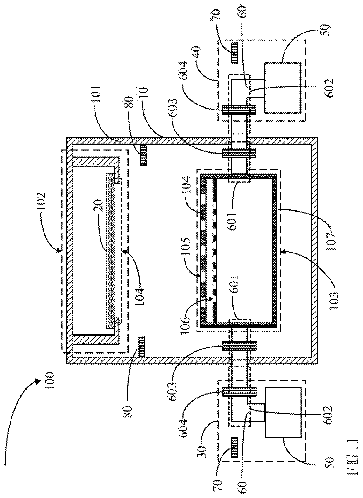
[0028]Please refer to FIG. 1 illustrating a schematic diagram of an evaporation device according to an embodiment of the present disclosure.

[0029]The evaporation device 100 includes a primary chamber 10 and two or more secondary chambers arranged around the primary chamber 10.

[0030]The primary chamber 10 includes a first shell 101, a platform 102 arranged in the first shell 101, and a line source crucible 103 arranged opposite the platform 102.

[0031]The platform 102 is configured to mount target substrates 20. Each of the target substrat...


PUM

PropertyMeasurementUnit
Lengthaaaaaaaaaa

Abstract

An evaporation device includes a primary chamber and two or more secondary chambers at both sides of the primary chamber. The secondary chamber is configured to supply the disposition material in a disposition process. One or more of the secondary chambers serve as an alternative disposition source. When the disposition material in one or more of the secondary chambers is nearly empty, the alternative disposition source in the other secondary chamber starts to operate.

Description

BACKGROUND1. Field of the Disclosure[0001]The present disclosure relates to a field of manufacturing a panel, and more particularly, to an evaporation device.2. Description of the Related Art[0002]The main fabrication of an organic light-emitting diode (OLED) device is to heat an evaporation coating.[0003]A chamber is opened to feed the evaporation material to the evaporation device whenever the evaporation material is nearly consumed. The evaporation device is a high vacuum coating device so the working pressure needs to be less than 5*10−5 pascal (Pa). It takes one to two days to reduce the working pressure in the evaporation source, and it spends longer time to feed the evaporation material each time, which limits the productivity of the evaporation device.[0004]Therefore, it is necessary to propose a new evaporation device to deal with the above problems.SUMMARY[0005]The present disclosure proposes an evaporation device to solve the problem that the productivity of the evaporati...

Claims


Application Information

Patent Timeline
IPC IPC(8): C23C14/24C23C14/54
CPCC23C14/243C23C14/246C23C14/54C23C14/26C23C14/12
Inventor XU, CHAO
Owner WUHAN CHINA STAR OPTOELECTRONICS SEMICON DISPLAY TECH CO LTD
Why Eureka
Try Eureka