
Multi-core optical connector and optical cable connection method

a multi-core, optical connector technology, applied in the direction of optics, instruments, optical light guides, etc., can solve the problems of increasing the workload of connecting with one cable, affecting the quality of optical cables, so as to reduce the workload of connecting, reduce the space of connecting portions, and reduce the connection time

Active Publication Date: 2021-11-04
NIPPON TELEGRAPH & TELEPHONE CORP
View PDF3 Cites 0 Cited by
  • Summary
  • Abstract
  • Description
  • Claims
  • Application Information

AI Technical Summary

Benefits of technology

The present invention is a mechanism that connects multiple optical fibers to a single optical cable, which reduces the workload of connection and the space needed for the connection. This results in faster installation and a more compact connection.

Problems solved by technology

In a case where an optical fiber is installed, it is exceedingly difficult to install with one cable when the installation distance is extended, and it is necessary to provide a connection point for each certain distance.
The minimum units of the fusion splicing and the MT connector connection are four fibers or eight fibers, and thus, there is a problem that it takes time and labor to perform a connection work.
Thus, there is a disadvantage that the connection portion has a diameter many time larger than the optical cable.

Method used


Image

  • Multi-core optical connector and optical cable connection method
  • Multi-core optical connector and optical cable connection method
  • Multi-core optical connector and optical cable connection method

Examples


Embodiment Construction

[0036]Hereinafter, an embodiment of the present invention will be described with reference to the drawings. The embodiment to be described below are examples of the present invention, and the present invention is not limited to the following embodiment. In this specification and the drawings, it is assumed that constituent elements having the identical reference signs are identical.

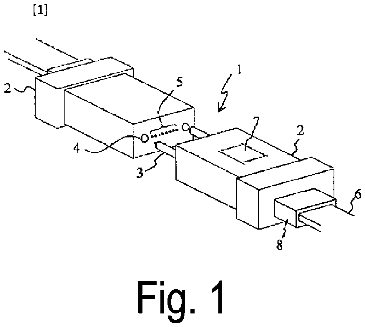
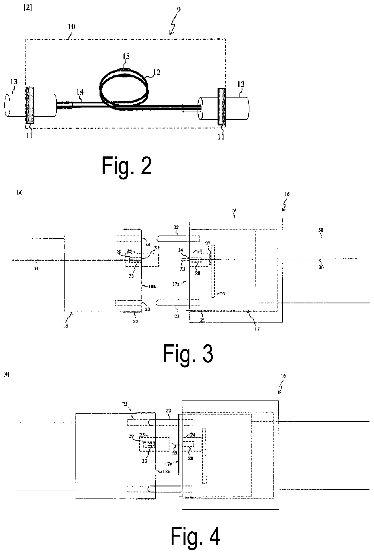
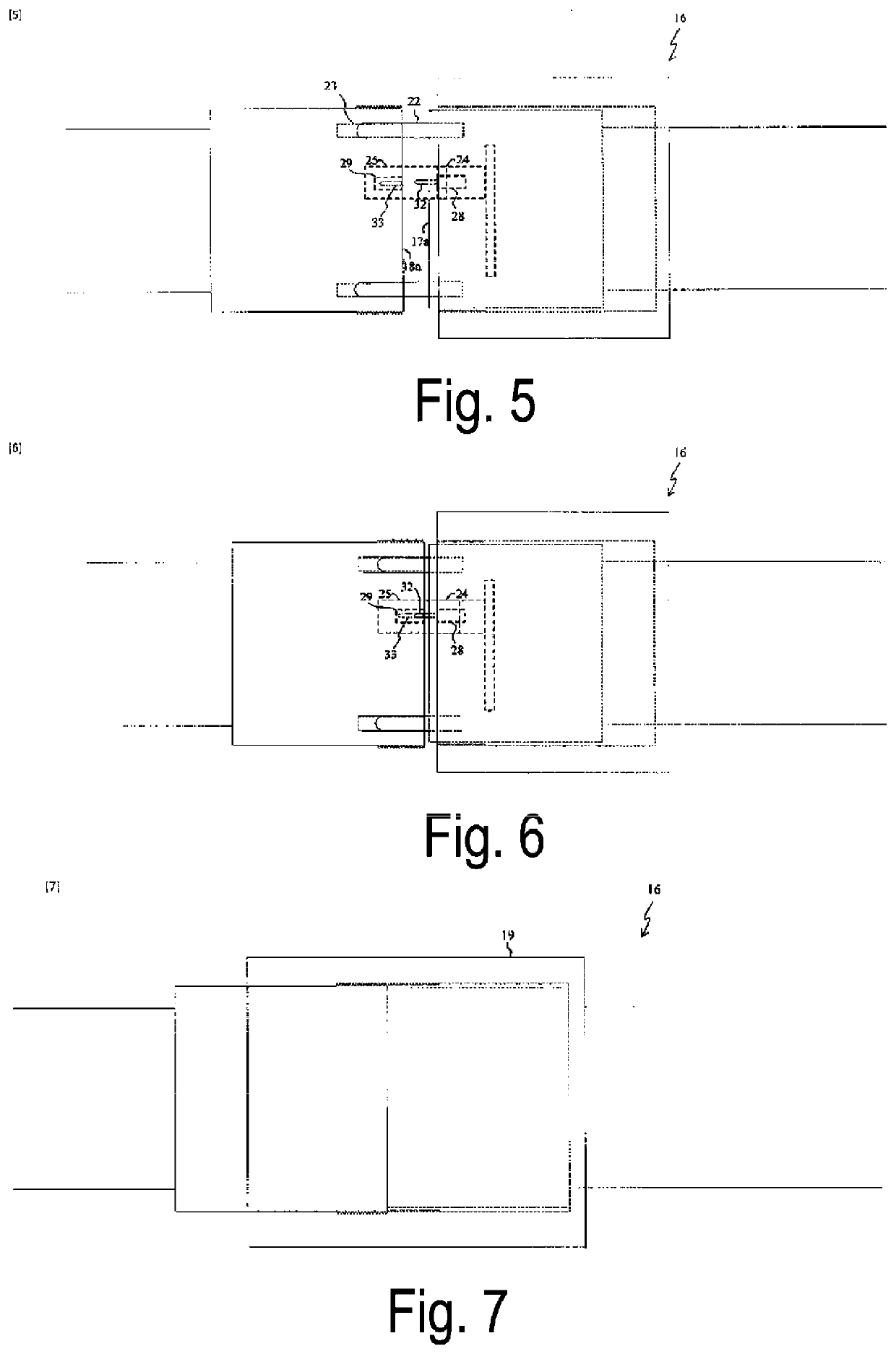
[0037]FIG. 3 is a diagram for describing an optical connector 16 for an optical cable of the present embodiment. The optical connector 16 for an optical cable is a multifiber optical connector that connects a plurality of optical fiber end faces appearing on a connection surface 17a of a first connector unit 17 and a plurality of optical fiber end faces appearing on a connection surface 18a of a second connector unit 18 by connecting the first connector unit 17 with the second connector unit 18, and has the following characteristics.

Optical connector ferrules (28 and 29) that group the optical fiber end f...


PUM

PropertyMeasurementUnit
forceaaaaaaaaaa
refractive indexaaaaaaaaaa
shapeaaaaaaaaaa

Abstract

An object is to provide a multifiber optical connector and an optical cable connection method capable of reducing a connection time and reducing an installation space of a connection portion. The multifiber optical connector according to the present invention includes three position adjustment units, and performs rough alignment to fine alignment of optical fiber end faces by using sequentially these position adjustment units when optical cables are connected. The multifiber optical connector simultaneously connects the end faces of the plurality of optical fibers included in the optical cables, and thus, an extra optical fiber tape is not present, and a closure needed in the related art is not necessary.

Description

CROSS REFERENCE TO RELATED APPLICATIONS[0001]This application is a 371 U.S. National Phase of International Application no. PCT / JP2019 / 039847, filed Oct. 9, 2019, which claims priority to Japanese Patent Application No. 2018-200363, filed Oct. 24, 2018. The entire disclosures of the above applications are incorporated herein by reference.TECHNICAL FIELD[0002]The present disclosure relates to a multifiber optical connector and an optical cable connection method for connecting optical cables.BACKGROUND ART[0003]Optical cables are currently used in various locations, and optical cables such as 400 fibers, 1000 fibers, and 2000 fibers have also been practiced. In a case where an optical fiber is installed, it is exceedingly difficult to install with one cable when the installation distance is extended, and it is necessary to provide a connection point for each certain distance. Optical fibers included in the optical cables mainly have a tape shape, and a technology for collectively conn...

Claims


Application Information

Patent Timeline
Patent Type & Authority Applications(United States)
IPC IPC(8): G02B6/40G02B6/38
CPCG02B6/403G02B6/3882G02B6/3885G02B6/3873
Inventor TAKAYA, MASAAKIKATAYAMA, KAZUNORIABE, YOSHITERUKOYAMA, RYOFUKAI, CHISATOYAMADA, YUSUKE
Owner NIPPON TELEGRAPH & TELEPHONE CORP
Learn More