System and method for repurposing 120vac wiring architecture to retrofitable low voltage DC power 2-wire LED dimming

a technology of led dimming and wiring architecture, applied in the field of led dimming, can solve the problems of low-end gradient performance deterioration, low-level gradient performance deterioration, and existing led lamp retrofit (screw-in) dimming designed to be dimmed by phase cut or sine wave dimmers, etc., to achieve consistent low-level gradient performance, short on-time pwm signals, and high dimming ratio

Active Publication Date: 2021-11-04
EPRAD
View PDF2 Cites 0 Cited by
  • Summary
  • Abstract
  • Description
  • Claims
  • Application Information

AI Technical Summary

Benefits of technology

[0005]The invention disclosed herein overcomes the problems described above. The power delivered to the lamps is directly usable by the LED(s), thus, no signal conversion is required by the lamps. The LED(s) in all lamps on the circuit receive the same signal from an external driver. The current commercially available lamps respond well to very short on-time PWM signals. This allows for a very high dimming ratio and consistent low-level gradient performance not achievable by designs with integrated drivers. The present invention provides a system and method for Low Power PWM dimming of at least one LED lamp in a circuit previously built and designed to carry 120 VAC power. This invention a

Problems solved by technology

Existing retrofit (screw-in) LED lamps designed to be dimmed by phase cut or sine wave dimmers do not provide a full range of gradient dimming required for precise premise applications such as theatre auditoriums.
In many examples of the current state of the art, the pop-on and drop-out thresholds vary dramatically between lamps, resulting in inconsistent low-end gradient performance, where some lamps exhibit zero light whi

Method used


Image

  • System and method for repurposing 120vac wiring architecture to retrofitable low voltage DC power 2-wire LED dimming
  • System and method for repurposing 120vac wiring architecture to retrofitable low voltage DC power 2-wire LED dimming

Examples


Embodiment Construction

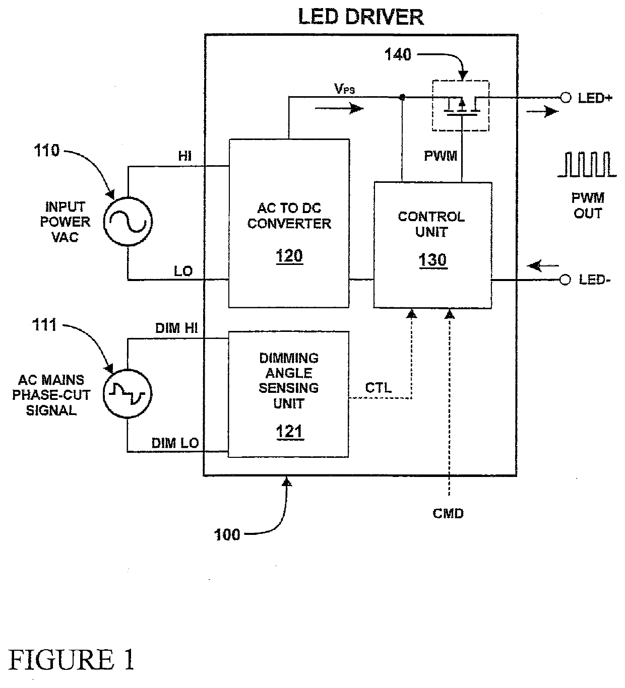
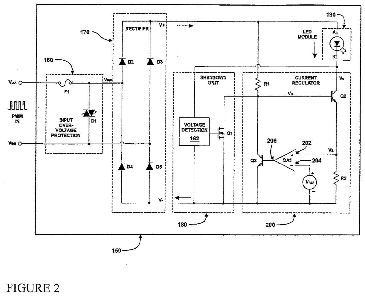
[0019]FIG. 1 shows LED driver 100 which is electrically connected to an AC power source 110. The LED driver 100 output terminals LED+ and LED− electrically connect to a plurality of LED lamps 150 as described in FIG. 2. The AC power source 110 is electrically connected to the AC to DC converter 120 where the AC power is converted to filtered and regulated DC power VPS for the control unit 130 and the power switch 140.

[0020]The power switch 140 is electrically connected to the AC to DC converter 120 DC power output VPS. The control unit 130 is electrically connected to the power switch 140. The power switch 140 is turned ON or OFF according to the pulse width modulation PWM signal from the control unit 130 in order to connect or disconnect the DC power (VPS) from the AC to DC converter 120 to the positive output terminal LED+ of the LED driver 100. In the present disclosure, the power switch 140 may be implemented with a P-type metal-oxide semiconductor (PMOS), in which the gate term...


PUM


Abstract

A 2-Wire LED dimming system and method re-purposes existing 120V AC architecture and hardware to carry low voltage PWM gradient DC power to the LED lamps provides a consistent gradation over a 0-100% dimming range. An LED Driver is electrically connected to an AC power source and connect to at least one LED lamp. The AC power source is electrically connected to an AC to DC converter where the AC power is converted to filtered and regulated DC power for the control unit and the power switch. The power switch is electrically connected to the AC to DC converter DC power output. The control unit is electrically connected to the power switch which is turned ON or OFF according to the pulse width modulation PWM signal from the control unit in order to connect or disconnect the DC power from the AC to DC converter.

Description

CROSS-REFERENCE TO RELATED APPLICATION[0001]The present application claims the benefit to U.S. Provisional Patent Application No. 62 / 750,027 filed on Oct. 24, 2018, which is incorporated herein by reference in its entirety.FIELD OF THE INVENTION[0002]The invention relates to LED dimming in environments requiring expansive and precise dimming gradation and, more particularly, to a system and method for re-purposing existing 120 VAC load wiring architecture and fixtures through the deployment of low voltage PWM power. This invention embodies a means to ameliorate conditions indicative of series voltage drop, eliminate “drop-out,”“pop-on” and flicker conditions, thus providing to the user a desired lighting scene ranging from zero light to 100% brightness in precise gradations.BACKGROUND OF THE INVENTION[0003]Existing retrofit (screw-in) LED lamps designed to be dimmed by phase cut or sine wave dimmers do not provide a full range of gradient dimming required for precise premise applica...

Claims


Application Information

Patent Timeline
IPC IPC(8): H05B45/3577H05B47/24H05B45/325H05B44/00
CPCH05B45/3577H05B45/325H05B47/24H05B45/3574H05B45/10H05B45/31H05B45/59H05B45/50Y02B20/30
Inventor PERRIN, III, JAMES B.
Owner EPRAD
Why Eureka
Try Eureka